Bottle pipe conveying mechanism for full automatic heating blowing machine

A technology of conveying mechanism and stretch-blow machine, which is applied in the field of plastic machinery, can solve problems such as inaccurate positioning of stretch-blow mechanism, elongated transmission chain, complex equipment structure, etc., and achieve the effects of saving heating power, simplifying structure and compact structure

Inactive Publication Date: 2009-09-23
王自强
View PDF0 Cites 3 Cited by
  • Summary
  • Abstract
  • Description
  • Claims
  • Application Information

AI Technical Summary

Problems solved by technology

In the prior art, the support for installing the bottle tube is a transmission chain. The support seat is connected to the outside of the transmission chain. The bottle tube mouth is inserted on the support seat. The power to drive the bottle tube support is the motor and the sprocket. The running route of the bottle tube heating It is a circular route composed of a transmission chain and a sprocket, and the output of the stretch blowing mechanism and the formed bottle is also on the circular route of the chain. The main disadvantages of this type of structure are: first, the transmission chain will be stretched during long-term operation, Especially after stretching, the positioning of the stretching and blowing mechanism is not accurate; the second is that the circular route formed by the chain and the sprocket makes the heating area of ​​the bottle tube very long, especially when processing multiple bottles at one time. The volume is very large and takes up a lot of workshops; the third is that the bottle tube needs to stop moving forward when it enters the stretching and blowing stage, that is, the circular motion is intermittent, and a stepping motor is generally used to drive the sprocket, the equipment structure is complicated, the investment is large, and the control requirements are high.

Method used


Image

  • Bottle pipe conveying mechanism for full automatic heating blowing machine
  • Bottle pipe conveying mechanism for full automatic heating blowing machine

Examples


Embodiment Construction

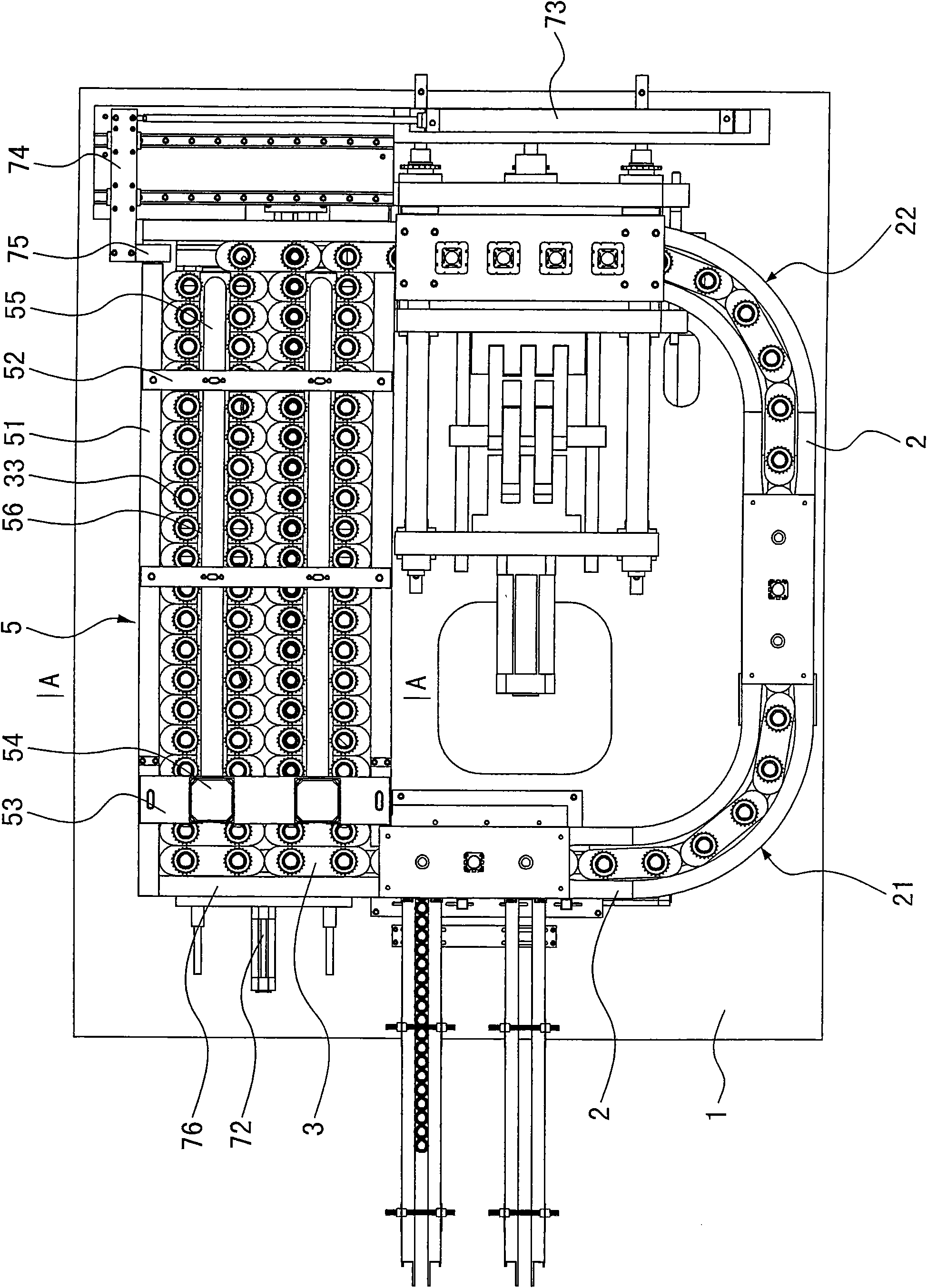
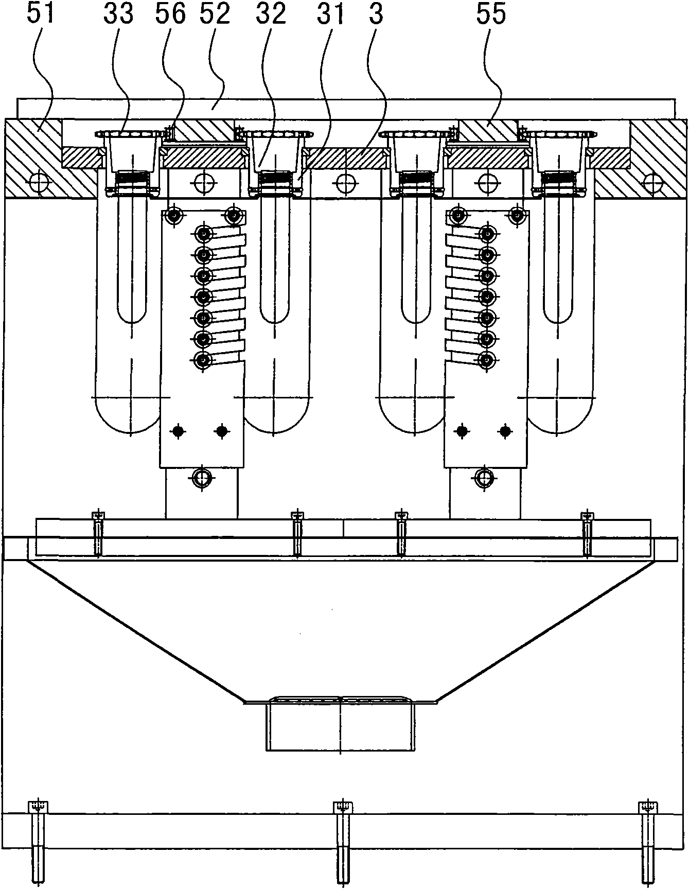
[0009] The invention relates to a bottle tube conveying mechanism of a fully automatic heating stretch blowing machine, such as figure 1 , figure 2 As shown, it includes frame 1, on which the bottle tube conveying track is installed, and the bottle tube support is installed in the track. The bottle tube support is driven by power. The track is divided into feeding area, heating area, stretch blow molding area and bottle ejection The area is characterized in that the track is a slide rail 2, and the support includes a slider 3, a rotating shaft 31 is installed in the sliding block, and a bottle insertion tube shaft hole 32 is formed in the rotating shaft, and there is a self- Runner 33, bottle tube supporting member is promoted by cylinder in slide rail 2, and slide block 3 enters heating zone 5 and changes into horizontal arrangement and advances, and the rotating shaft 31 after horizontal arrangement is 2 rows or 4 rows or more than 4 rows. In this scheme, the support for i...


PUM


Abstract

The invention relates to a bottle pipe conveying mechanism for a full automatic heating blowing machine. The bottle pipe conveying mechanism comprises a machine frame on which a bottle pipe conveying track is arranged. A bottle pipe supporting piece is arranged in the track and driven by a dynamic force. The track is divided into a charging zone, a heating zone, a blowing and forming zone and a bottle leaking zone. The bottle pipe conveying mechanism is characterized in that: the track is a sliding track; the supporting piece comprises sliders and rotating shafts are arranged in the sliders; the rotating shafts are provided with shaft holes for holding bottle pipes; free wheels wheels are arranged on the rotating shafts; the bottle pipe supporting piece is driven to move in the sliding track through cylinders; after entering the heating zone, the sliders are changed into a status of advancing side by side; and the sliders have 2 rows or 4 rows or more than 4 rows of rotating shafts in transverse arrangement. The technical proposal brings about a small complete machine size and a high thermal utilization factor. The bottle pipe conveying mechanism has electricity conservation, reliable operation, discontinuous advance, and correct positioning.

Description

technical field [0001] The invention relates to a conveying mechanism for a bottle tube of a fully automatic heating stretch-blow machine, which belongs to the field of plastic machinery and is mainly used for processing hollow plastic containers such as mineral water bottles and oil bottles. Background technique [0002] Hollow plastic containers such as mineral water bottles and oil bottles are processed by injection stretch blowing. First, plastic raw materials (such as PET, etc.) are injected into bottle tubes by an injection molding machine, and then the bottle tubes are heated by a heater, and then heated by a stretch blowing machine. The final bottle tube stretch blow molding, automatic heating stretch blow machine is a combination of heater and stretch blow machine on the same machine, which can be divided into bottle tube feeding mechanism, bottle tube conveying mechanism, stretch blow molding mechanism and bottle ejection mechanism . The bottle tube conveying mech...

Claims


Application Information

Patent Timeline
Patent Type & Authority Applications(China)
IPC IPC(8): B29C49/42B29C31/08B29L22/00
Inventor 王自强
Owner 王自强
Why Eureka
Try Eureka