RH bottom blowing argon vacuum circulating degasser

A technology of vacuum cycle degassing and bottom blowing argon, applied in the field of metallurgy, can solve the problem that the diameter of the rising pipe cannot be infinite, and achieve the effect of shortening the mixing time, speeding up the removal, and improving the degassing.

Inactive Publication Date: 2009-09-23
NORTHEASTERN UNIV
View PDF0 Cites 18 Cited by
  • Summary
  • Abstract
  • Description
  • Claims
  • Application Information

AI Technical Summary

Problems solved by technology

And because the diameter of the riser cannot be infinitely large, there is a saturated argon blowing volume; how to increase the saturated circulation flow rate of the degassing device has become an urgent problem to be solved

Method used


Image

  • RH bottom blowing argon vacuum circulating degasser
  • RH bottom blowing argon vacuum circulating degasser
  • RH bottom blowing argon vacuum circulating degasser

Examples


Embodiment 1

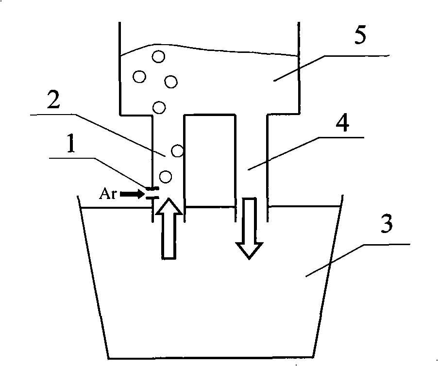
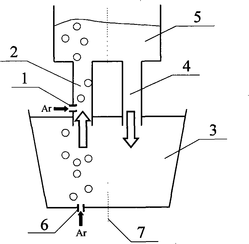
[0023] The structure of the RH bottom blowing argon vacuum cycle degassing device is as follows: figure 2 As shown, it includes a ladle 3 and a vacuum chamber 5 , the bottom of the vacuum chamber 5 is provided with an ascending pipe 2 and a descending pipe 4 , and the ascending pipe 2 is connected to the side argon blowing device 1 . Wherein, the bottom wall of the ladle 3 is provided with a nozzle 6, and the nozzle 6 is connected with an argon blowing device at the bottom. The straight line passing through the center of the bottom wall of the ladle and parallel to the centerline of the riser and the centerline of the downcomer is the centerline 7 of the ladle.

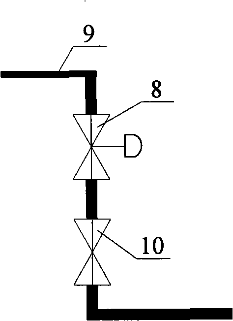
[0024] Argon blowing device at the bottom of the ladle such as image 3 shown. The bottom argon blowing device includes a regulating valve 8 , an argon blowing pipe 9 and a shut-off valve 10 . The nozzle 6 communicates with the argon blowing pipe 9 , and the argon blowing pipe 9 is provided with a shut-off valve 1...

Embodiment 2

[0034] The structure of the RH bottom blowing argon vacuum cycle degassing device is as follows: Figure 4 As shown, the bottom wall of the ladle 3 is provided with a ventilating brick 11, and the ventilating brick 6 is connected with an argon blowing device, and the other parts are the same as in the first embodiment.

[0035] Argon blowing device at the bottom of the ladle such as image 3 shown. The bottom argon blowing device includes a regulating valve 8 , an argon blowing pipe 9 and a shut-off valve 10 . The ventilation brick 6 communicates with the argon blowing pipe 9, and the argon blowing pipe 9 is provided with a shut-off valve 10 and a regulating valve 8.

[0036] The bottom wall of the ladle is provided with a breathable brick 11, and the breathable brick 11 is connected to the bottom argon blowing device; the breathable brick 11 is located on the side where the rising pipe 2 projects on the bottom wall of the steel ladle 3, that is, the left side of the center ...

Embodiment 3

[0042] The RH bottom blowing argon vacuum circulation degassing device is the same as that of Example 1, the difference is that: the bottom wall of the ladle is provided with two nozzles, and the inner diameter of the gas outlet of the nozzles is 5mm; each nozzle is connected to a bottom argon blowing device; two nozzles It is located on the side of the projection of the riser on the bottom wall of the ladle, that is, on the left side of the center line 7 of the ladle; the centers of the inner holes of the two nozzles and the center of the bottom wall are on the same straight line.

[0043] The size and structure of the RH bottom blowing argon vacuum circulation degassing device are as follows: Image 6 shown, where S no1 is the distance from the argon blowing position at the bottom of the first ladle (the center of the position where the nozzle is located) to the center of the ladle, and S no1 =535mm; S no2 is the distance from the argon blowing position at the bottom of th...


PUM


Abstract

The invention relates to an RH bottom argon blowing vacuum circulating degasser belonging to the technical field of metallurgy and comprising a steel ladle and a vacuum chamber, wherein the bottom wall of the steel ladle is provided with a nozzle or an air brick, and the nozzle or the air brick is connected with an argon blowing device and positioned at one side of the projection of an ascending tube of the vacuum chamber on the bottom wall of the steel ladle. The RH bottom argon blowing vacuum circulating degasser can effectively enhance the circular flow of the RH bottom argon blowing vacuum circulating degasser, increase the internal stirring of the RH vacuum circulating degassing steel ladle, shorten the blending time, accelerate the elimination of deoxidation type inclusions inside the RH vacuum circulating degassing steel ladle and enhance the degassing and the decarburization speed.

Description

technical field [0001] The invention belongs to the technical field of metallurgy, in particular to an RH bottom blowing argon vacuum circulation degassing device. Background technique [0002] With the demand for ultra-low carbon steel and other special steel types in the market, RH vacuum refining has become one of the important refining equipment outside the furnace. The basic principle of the existing RH vacuum degassing device is to blow argon gas through the argon channel installed in the riser, and drive the molten steel in the ladle into the riser under the action of vacuum, and then pass through the vacuum chamber, and then the downcomer Go back to the ladle to complete a cycle, so as to realize the batch processing of molten steel. At present, the main functions of RH refining include the following aspects: dehydrogenation, denitrogenation, decarburization under vacuum, powder spraying desulfurization, dephosphorization, deoxidation and removal of deoxidized inclu...

Claims


Application Information

Patent Timeline
Patent Type & Authority Applications(China)
IPC IPC(8): C21C7/10C21C7/072
Inventor 雷洪赫冀成耿佃桥
Owner NORTHEASTERN UNIV
Why Eureka
Try Eureka