Jet-steam compound engine with spray liquid evaporating on hot wall

A jet engine and engine technology, applied in steam engine devices, engine components, combustion engines, etc., can solve the problems of low thermal efficiency and high fuel consumption of jet engines, and achieve the effects of high thermal efficiency, low vibration and simple structure

Inactive Publication Date: 2009-09-23
王鑫弘
View PDF0 Cites 7 Cited by
  • Summary
  • Abstract
  • Description
  • Claims
  • Application Information

AI Technical Summary

Problems solved by technology

[0002] Existing jet engines have high fuel consumption and low thermal efficiency. After the gas passes through the turbine, the temperature and pressure drop suddenly, and about 75% of the gas energy is converted into mechanical energy, which is used to drive the compressor, fan and other accessories, and the remaining gas energy goes to generate thrust

Method used


Image

  • Jet-steam compound engine with spray liquid evaporating on hot wall
  • Jet-steam compound engine with spray liquid evaporating on hot wall
  • Jet-steam compound engine with spray liquid evaporating on hot wall

Examples


Embodiment Construction

[0020] The present invention will be described in further detail below in conjunction with accompanying drawing and specific embodiment: the present invention example has five embodiment examples;

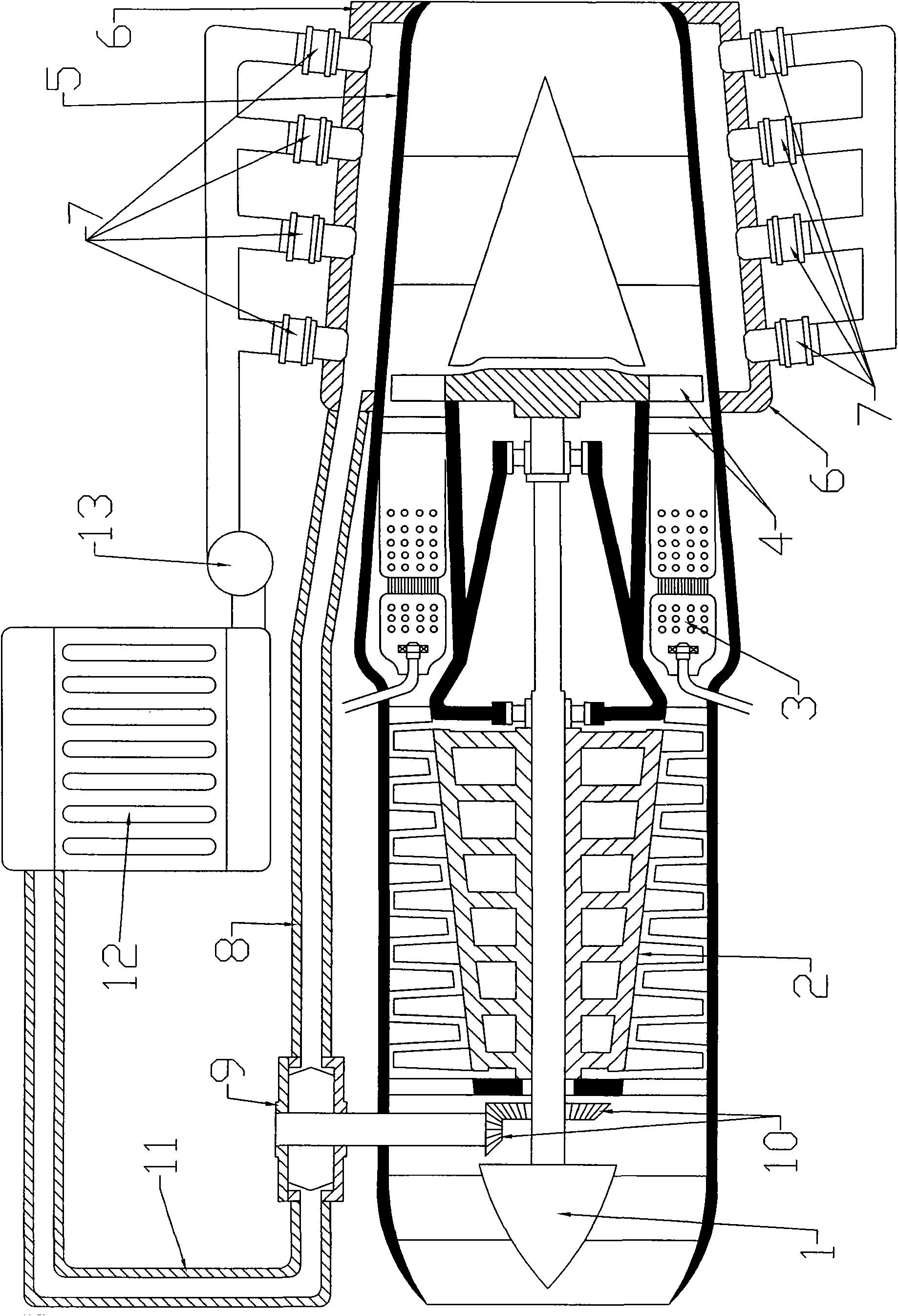
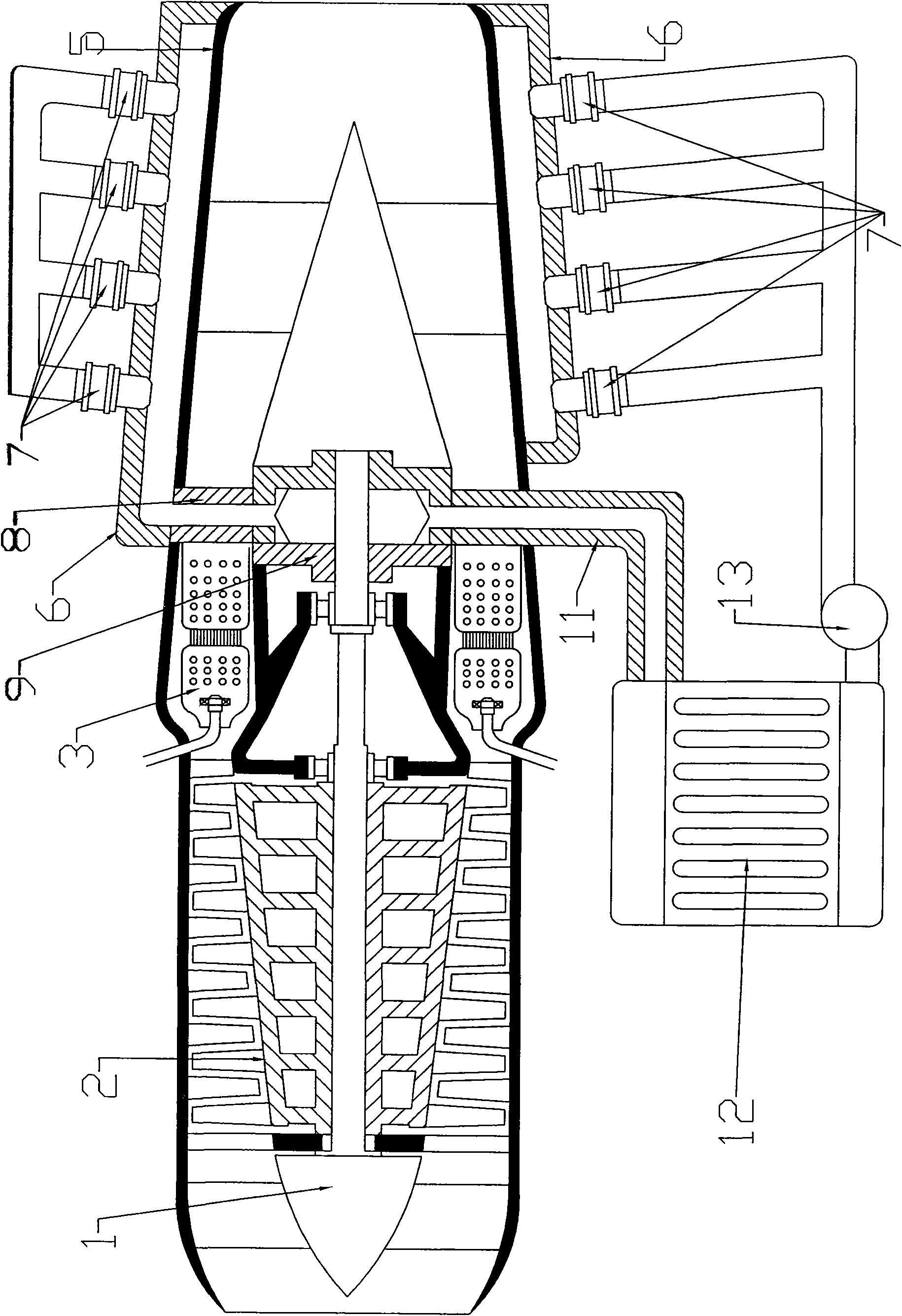
[0021] figure 1 The first embodiment shown is that the airtight interlayer casing 6 is sheathed on the outer circumference of the exhaust nozzle casing 5 of the air jet engine 1, and it forms an evaporation chamber with the exhaust nozzle casing 5, and the airtight interlayer casing 6 is from the turbine 4 to the Exhaust nozzle ends at 5 ports. Several spray nozzles 7 are arranged on the outer periphery of the airtight sandwich casing 6, and extend into the evaporation chamber. Inlet connection. The steam turbine 9 is arranged outside the shell of the air jet engine 1, and the power shaft of the steam turbine 9 extends into the air jet engine 1 shell, and is connected to the front end of the compressor 2 of the air jet engine 1 through a bevel gear 10. The exhaust pipe 11 of the...


PUM


Abstract

The invention relates to a jet-steam compound engine with spray liquid evaporating on a hot wall. The compound engine mainly consists of an aerojet engine, a gas compressor, a combustion chamber, a turbine, an exhaust cone, a closed interlayer shell, a spraying nozzle, a steam conduit, a steam turbine, a cone gear, a steam discharge pipe, a condensation radiator, a water pump, a tail opening interlayer shell, a turboprop, a circular surrounding fixed housing, a steel pipe, a propeller, a turbo propeller fan engine, a petal type spray pipe, a circular tube housing, a steam turbine and other parts. The compound engine is high in heat efficiency, energy-saving, small in vibration, low in noise, simple in structure, mature in the technology and the like and can be widely applied to various airplanes and power generation plants.

Description

technical field [0001] The invention relates to a jet engine and steam engine composite engine for spraying liquid onto a hot wall for evaporation. Background technique [0002] Existing jet engines have high fuel consumption and low thermal efficiency. After the gas passes through the turbine, the temperature and pressure drop suddenly, and about 75% of the gas energy is converted into mechanical energy, which is used to drive the compressor, fan and other accessories, and the remaining gas energy goes to Generate thrust. Contents of the invention [0003] The purpose of the invention is to improve thermal efficiency and save energy by using the heat of jet engine. [0004] The principle is: the gas temperature of the jet engine is more than 2000 degrees to make the tail nozzle heat, and the high-speed evaporation device directly sprays the liquid onto the hot wall to utilize it, and the interlayer shell and the tail nozzle shell are installed outside the tail nozzle she...

Claims


Application Information

Patent Timeline
Patent Type & Authority Applications(China)
IPC IPC(8): F02G5/02F02C6/18F01K23/16
CPCY02T10/166Y02E20/18Y02T10/12
Inventor 王鑫弘
Owner 王鑫弘
Why Eureka
Try Eureka