Smoke exhaust heat utilization device of directly-fired triple effect machine

A heat and direct combustion technology, which is applied in the direction of machines using waste heat, machine operation mode, climate change adaptation, etc., can solve the problems of increased smoke exhaust loss and increased flue gas heat exhaust loss, etc., to reduce smoke exhaust loss, Effects of reducing fuel consumption and operating costs and improving utilization efficiency

Active Publication Date: 2010-07-21
SHUANGLIANG ECO ENERGY SYST CO LTD
View PDF0 Cites 0 Cited by
  • Summary
  • Abstract
  • Description
  • Claims
  • Application Information

AI Technical Summary

Problems solved by technology

[0003] Since the solution temperature of the direct-fired high-pressure generator of the direct-fired three-effect machine exceeds 200°C, and even reaches above 220°C, the exhaust gas temperature of the direct-fired high-pressure generator is much higher than that of the direct-fired double-effect machine, and even reaches the smoke exhaust temperature above 250°C. The temperature is more than 4% higher than that of the direct-fired double-effect machine, which greatly increases the heat loss of the flue gas

Method used


Image

  • Smoke exhaust heat utilization device of directly-fired triple effect machine
  • Smoke exhaust heat utilization device of directly-fired triple effect machine
  • Smoke exhaust heat utilization device of directly-fired triple effect machine

Examples


Embodiment Construction

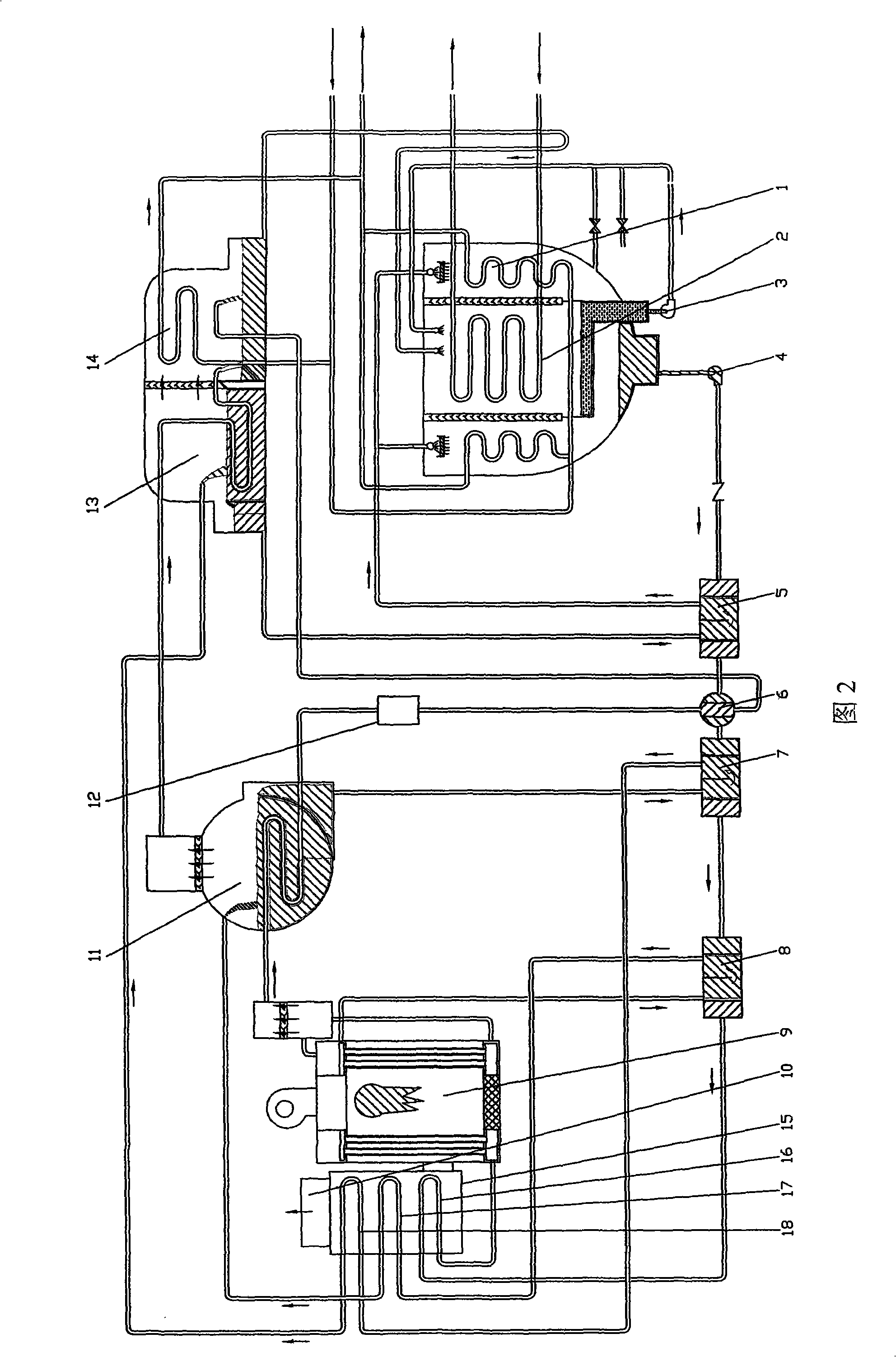
[0010] like figure 2 The solution flow shown in the figure is a direct-fired three-effect machine with a positive series flow, consisting of a direct-fired high-pressure generator 9, a medium-pressure generator 11, a low-pressure generator 13, an evaporator 2, an absorber 1, and a high-temperature solution heat exchanger 8 , medium temperature solution heat exchanger 7, low temperature solution heat exchanger 5 and connecting pipelines, pumps and valves. A smoke heat utilization device 15 is added in the flue gas outlet pipe 10 of the direct-fired high-pressure generator 9. The shell side of the smoke heat utilization device 15 is provided with high-temperature flue gas heat exchange tube bundles 16, medium-temperature flue gas Gas heat exchange tube bundle 17, low temperature flue gas heat exchange tube bundle 18. The tube side of the high-temperature flue gas heat exchange tube bundle 16 is arranged in series on the solution pipeline that exits the high-temperature solutio...


PUM


Abstract

The invention relates to a smoke exhaust heat utilization device of a directly-fired triple effect machine, comprising a directly-fired high pressure generator (9), a medium pressure generator (11), a low pressure generator (13), a high temperature solution heat exchanger (8), a medium temperature solution heat exchanger (7) and a low temperature solution heat exchanger (5). A smoke outlet pipe (10) of the directly-fired high pressure generator (9) is internally and additionally provided with a smoke exhaust heat utilization device (15); the shell side of the smoke exhaust heat utilization device (15) is sequentially provided with a high temperature smoke heat exchange tube bundle (16), a medium temperature smoke heat exchange tube bundle (17) and a low temperature smoke heat exchange tube bundle (18) upwards along the smoke flow direction; the tube side of the high temperature smoke heat exchange tube bundle (16) is arranged in series on a solution pipeline for entering and exiting the directly-fired high pressure generator (9); the tube side of the medium temperature smoke heat exchange tube bundle (17) is arranged in series on a solution pipeline for entering the medium pressure generator (11); and the tube side of the low temperature smoke heat exchange tube bundle (18) is arranged in series on a solution pipeline for entering the low pressure generator (13). The inventioncan further improve the fuel heat utilization ratio of the directly-fired triple effect machine, reduce the temperature of smoke exhaust and reduce the heat loss of smoke exhaust.

Description

(1) Technical field [0001] The invention relates to a direct-fired three-effect lithium bromide absorption type cold (hot) water unit exhaust heat utilization device. It belongs to the technical field of refrigeration equipment. (2) Background technology [0002] The previous direct-fired three-effect lithium bromide absorption cold (hot) water units (including chillers and cold and hot water units, the same below) (hereinafter referred to as direct-fired three-effect units) are as follows: figure 1 As shown, the heat of condensation of refrigerant vapor is utilized many times. Compared with the general steam double-effect lithium bromide absorption cold (hot) water unit, a high-pressure generator and a solution heat exchanger are added. The solution is heated separately in high-pressure, medium-pressure, and low-pressure generators. The high-pressure generator is heated by heat sources such as fuel oil, gas or high-temperature flue gas. The refrigerant steam generated hea...

Claims


Application Information

Patent Timeline
Patent Type & Authority Patents(China)
IPC IPC(8): F25B27/02
CPCY02A30/274
Inventor 毛洪财徐建虎
Owner SHUANGLIANG ECO ENERGY SYST CO LTD
Why Eureka
Try Eureka