
Flue gas waste heat recovery and negative energy consumption dust-removal system for electric stove

A waste heat recovery system and flue gas waste heat technology, applied in furnaces, waste heat treatment, furnace components, etc., can solve the problems of reducing the heat transfer efficiency and service life of the heating surface of the heat pipe, increasing the maintenance workload and operating resistance, and wasting energy. Achieve the effect of saving operation and maintenance costs, saving equipment investment, and ensuring normal and stable operation

Inactive Publication Date: 2009-09-23
BAOSTEEL ENG & TECH GRP
View PDF0 Cites 22 Cited by
  • Summary
  • Abstract
  • Description
  • Claims
  • Application Information

AI Technical Summary

Problems solved by technology

But in this way, a lot of energy is wasted due to the mixing of a large amount of air and the system becomes huge. More importantly, the flue gas of the electric furnace has not been dust-removed, and the high-temperature gas contains a large amount of fine cohesive dust and will Bonded to the heating surface of the heat pipe, which increases the maintenance workload and running resistance, and reduces the heat transfer efficiency and service life of the heating surface of the heat pipe

Method used


Image

  • Flue gas waste heat recovery and negative energy consumption dust-removal system for electric stove
  • Flue gas waste heat recovery and negative energy consumption dust-removal system for electric stove

Examples


Embodiment Construction

[0028] Attached below Figure 1~2 A preferred embodiment of the present invention will be described in detail.

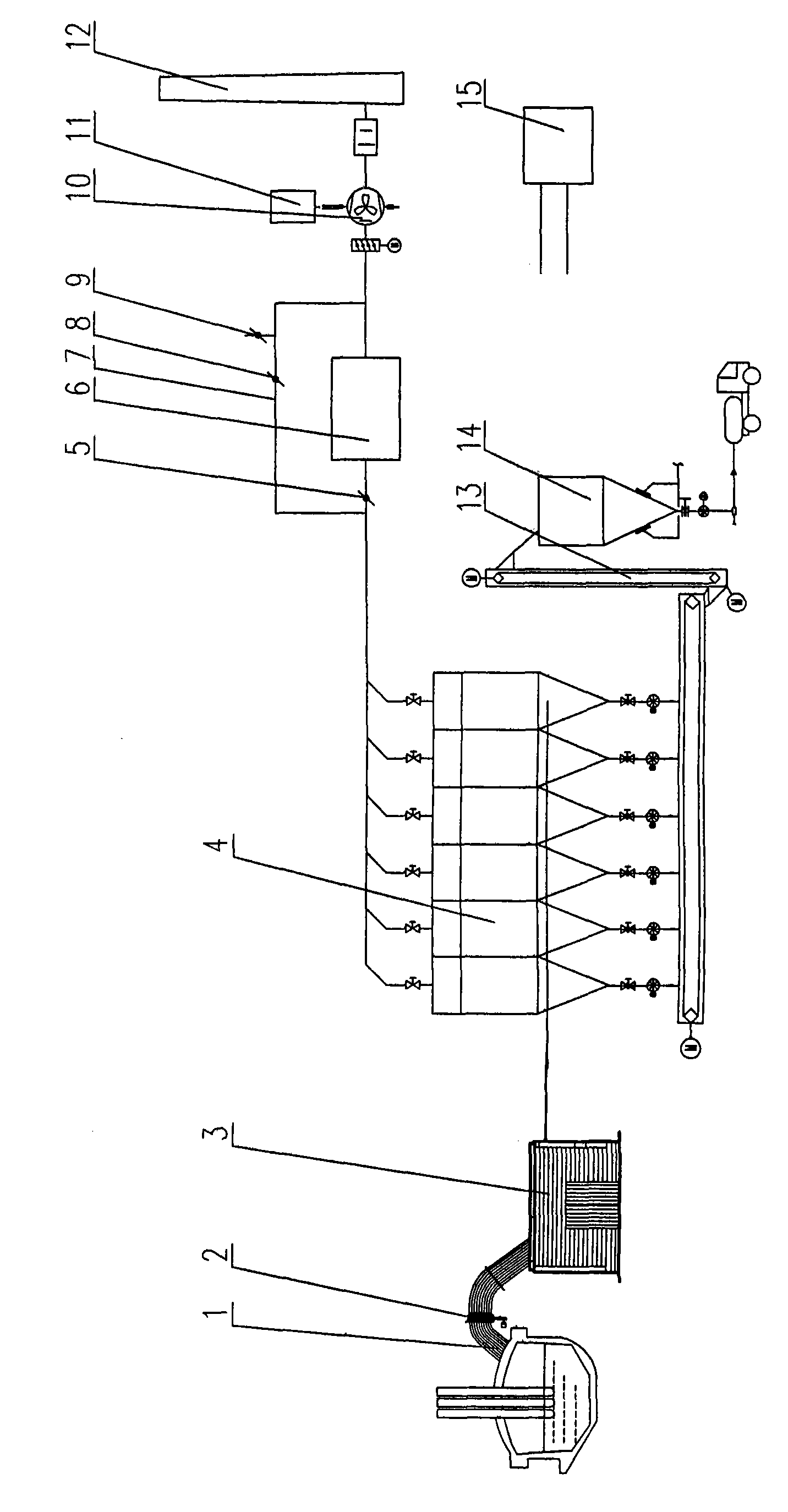
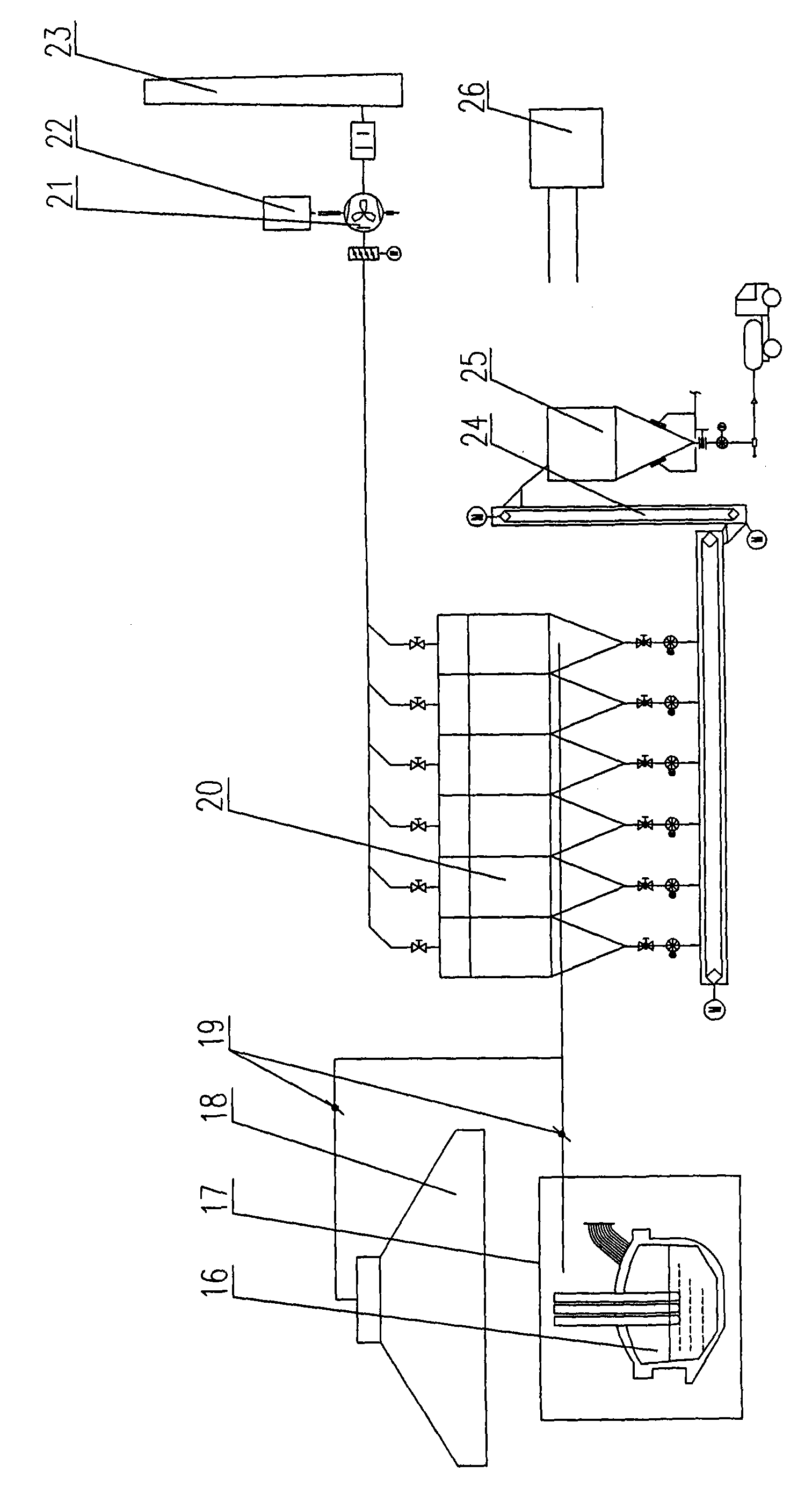
[0029] The invention divides the electric furnace flue gas waste heat recovery and negative energy consumption dust removal system into two parts, one part is the electric furnace flue gas primary dust removal and waste heat recovery system used to absorb the high temperature flue gas produced by the electric furnace in the smelting stage; the other part is used to absorb The electric furnace flue gas secondary dust removal system for the flue gas generated by the electric furnace during the feeding and tapping stages (including part of the flue gas escaping from the electric furnace cover during the smelting stage).

[0030] see figure 1 , the electric furnace flue gas primary dust removal and waste heat recovery system in the present invention is connected to the electric furnace smoke exhaust hole 1, and the electric furnace flue gas primary dust removal and was...


PUM


Abstract

The invention relates to a flue gas waste heat recovery and negative energy consumption dust-removal system for an electric stove, comprising a first flue gas dust-removal and waste heat recovery system for the electric stove which is connected with the smoke hole of the electric stove to absorb high temperature flue gas generated by the electric stove during smelting phase and a secondary flue gas dust-removal system for the electric stove which is in charge of absorbing the flue gas generated by the electric stove during charging and tapping phase. The first flue gas dust-removal and waste heat recovery system for the electric stove comprises a water cooling travelling tube, an evaporation cooling device, a high temperature resistant dust remover, a waste heat boiler, a dust removal fan and a chimney; wherein the evaporation cooling device replaces the original water cooling flue gas path and combustor. The secondary flue gas dust-removal system for the electric stove comprises a collecting cover, a dust remover worked at normal temperature, a dust removal fan and a chimney. The invention is high in dust removal efficiency and high in vapor recovery rate, saves a first cooling device and a secondary cooling device, reduces device investment and maintenance charge and prolongs the service life of the filter pocket of the dust remover.

Description

technical field [0001] The invention relates to the field of industrial furnace flue gas treatment and heat recovery, in particular to an electric furnace flue gas waste heat recovery and negative energy consumption dust removal system applied in the electric furnace steelmaking process of a metallurgical steel plant. Background technique [0002] At present, the production pace of electric furnaces in steel mills is generally accelerated, and the proportion of molten iron is increased, resulting in a substantial increase in the amount of flue gas during electric furnace smelting. For electric furnace dust removal, it mainly involves the recovery and non-recovery of waste heat from electric furnace flue gas. [0003] Most of the existing electric furnace flue gas waste heat is not recycled, and the high-temperature flue gas generated during electric furnace smelting is combined with the secondary dust removal of flue gas during electric furnace feeding and tapping to set up ...

Claims


Application Information

Patent Timeline
Patent Type & Authority Applications(China)
IPC IPC(8): F27D17/00B01D46/02B01D46/04B01D46/42
CPCY02P10/25
Inventor 王永忠戴鸿宽沈晓红朱军
Owner BAOSTEEL ENG & TECH GRP
Learn More