Energy storing device

An energy storage device and box technology, which is applied in thermal storage equipment, energy storage, damage protection, etc., can solve the problem that solar energy cannot be applied more widely, and achieve efficient heat storage (release), volume reduction, and energy storage capacity. improved effect

Inactive Publication Date: 2009-09-23
刘学来 +1
View PDF0 Cites 6 Cited by
  • Summary
  • Abstract
  • Description
  • Claims
  • Application Information

AI Technical Summary

Problems solved by technology

However, due to the discontinuity of its time, the utilization of solar energ

Method used


Image

  • Energy storing device
  • Energy storing device
  • Energy storing device

Examples


Embodiment Construction

[0018] The present invention will be further described below in conjunction with accompanying drawing by non-limiting embodiment:

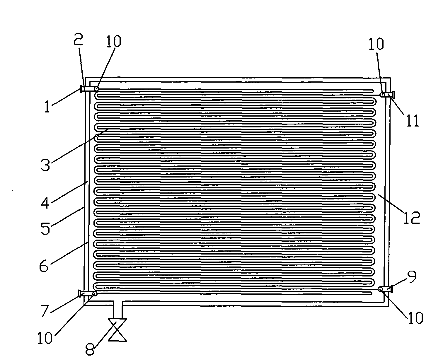
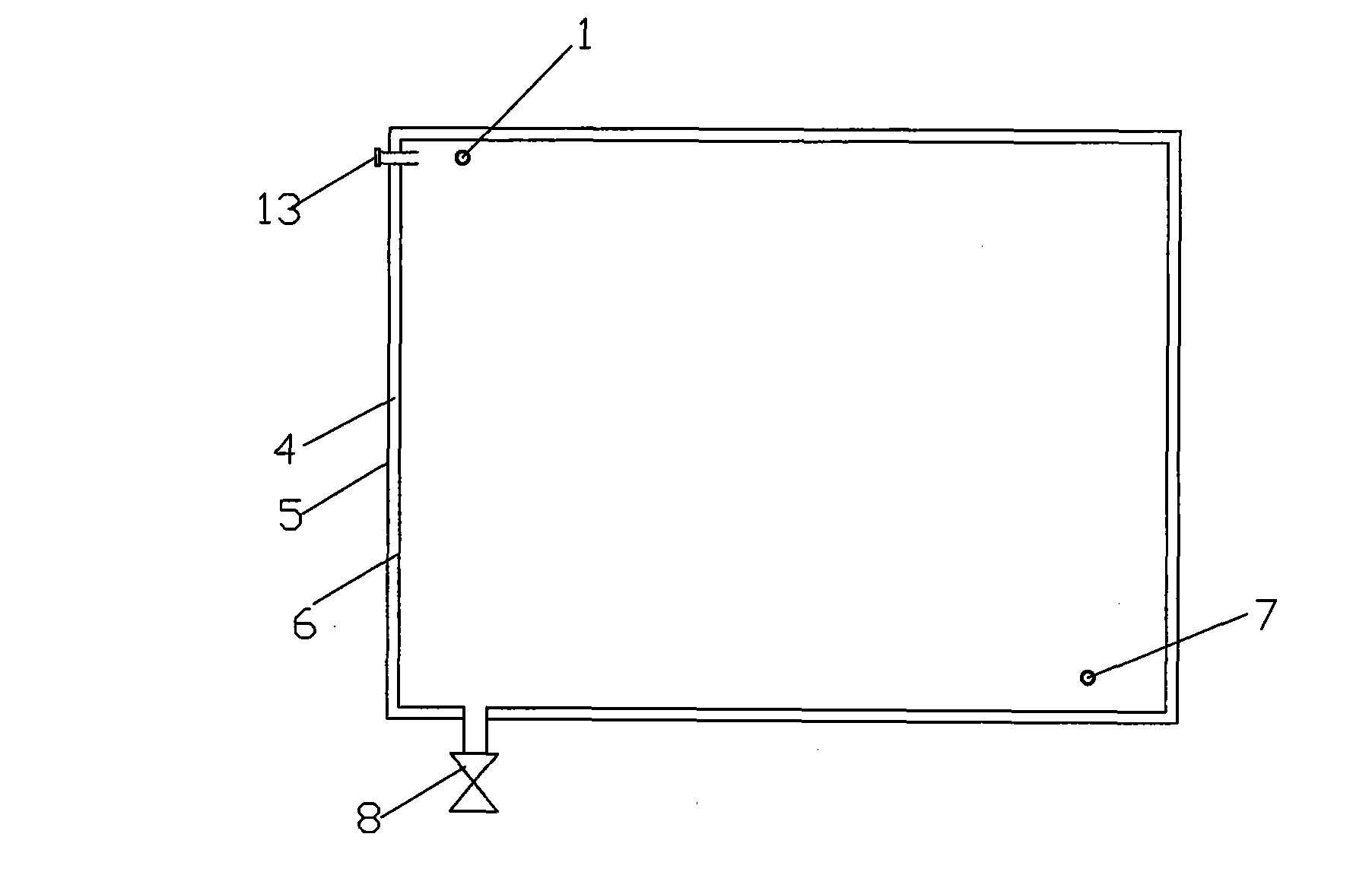
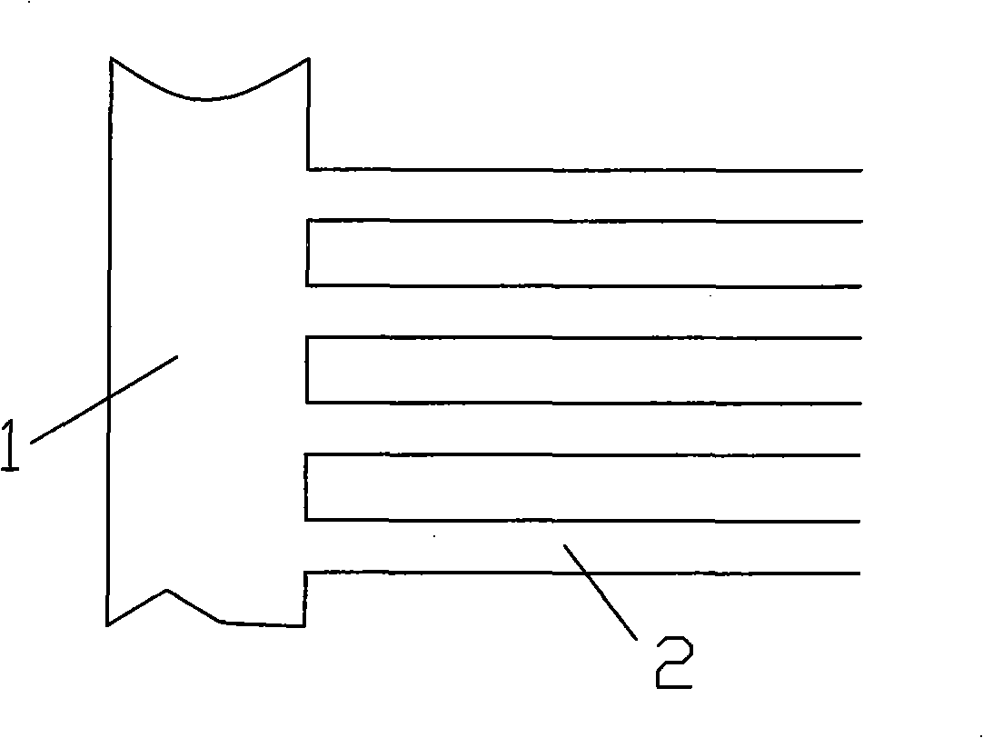
[0019] As shown in the drawings, an energy storage device includes a box body 6 made of PPR plastic, a stainless steel shell 5 is arranged outside the box body 6, and polyurethane insulation material 4 is filled between the shell 5 and the box body 6 , The polyurethane insulation layer can be filled with on-site foaming. The box 6 is provided with two sets of capillary heat exchange structures arranged countercurrently, each set of capillary heat exchange structures includes two connecting pipes 10 , and several capillary tubes 3 are connected in parallel between the two connecting pipes 10 . The material of the capillary heat exchange structure is corrosion-resistant PPR plastic, the outer diameter of the capillary 3 is 5-6 mm, and the distance between the capillaries of the two sets of capillary heat exchange structures is 12 mm. The box body 6...


PUM

PropertyMeasurementUnit
Outer diameteraaaaaaaaaa

Abstract

The invention discloses an energy storing device which is used for air conditioners and hot water supply. The energy storing device comprises a box body (6) and is characterized in that the box body (6) is internally provided with two sets of capillary pipe heat exchange structures which are respectively used for storing energy and discharging the energy; and a cavity of the box body is internally filled with a heat storage medium material capable of phase change. The energy storing device transmits heat to a phase change medium through one set of the capillary pipe heat exchange structures, and the phase change medium absorbs and stores the energy; and when a system needs the heat, the other set of the capillary pipe heat exchange structures can extract the heat from the energy storing device to meet the requirements of life or engineering. The energy storing device better compensates the defects of various energy utilizations such as solar thermal collectors, air source heat pumps, water resource heat pumps, and the like and stores the energy with high efficiency and high capacity according to the requirements by adopting the advanced phase change and capillary pipe heat exchange technology so as to adjust the timeliness in the process of using the energy. The energy storing device has high heat exchange efficiency and heat storage capability and small volume.

Description

technical field [0001] The invention relates to an energy storage device, in particular to an energy storage device for air conditioning and hot water supply. Background technique [0002] Water source heat pump has the characteristics of high energy efficiency ratio (COP≥5), and has been developed and applied rapidly in air conditioning and hot water supply. However, due to the limitation of water resources, its popularization and application have been greatly restricted at the same time. Therefore, in most cases, it is more convenient for people to use air source heat pumps and solar collectors in the supply of air conditioning, heating and domestic hot water. When the outdoor ambient temperature is low and has a certain humidity, the surface cooler of the air source heat pump is prone to frost; when heating water, the efficiency is relatively low and energy consumption is large, and even direct heating with electric energy is not conducive to energy saving . However, w...

Claims


Application Information

Patent Timeline
IPC IPC(8): F28D20/02F28F21/06F28F1/00F28F19/00
CPCY02E70/30Y02E60/145Y02E60/14
Inventor 刘学来李永安李继志
Owner 刘学来
Why Eureka
Try Eureka