Excess polymer ring removal during ophthalmic lens manufacture

A technology for ophthalmic lenses and polymers, which can be used in applications, home appliances, and other home appliances, and can solve problems such as supplying monomers or reaction mixtures

Inactive Publication Date: 2009-09-23
JOHNSON & JOHNSON VISION CARE INC
View PDF18 Cites 0 Cited by
  • Summary
  • Abstract
  • Description
  • Claims
  • Application Information

AI Technical Summary

Problems solved by technology

[0008] But the specific problem is feeding too much monomer or reaction mixture into the female mold

Method used


Image

  • Excess polymer ring removal during ophthalmic lens manufacture
  • Excess polymer ring removal during ophthalmic lens manufacture
  • Excess polymer ring removal during ophthalmic lens manufacture

Examples


Embodiment Construction

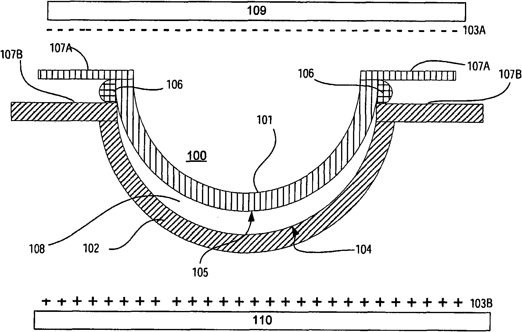
[0019] The use of electrostatic charge differences between dies used to form ophthalmic lenses to reduce the incidence of hole defects has been described separately. However, in accordance with the present invention, the use of a positive electrostatic charge on the front curve module may have the beneficial effect of reducing the incidence of hole defects, but may also disadvantageously increase excess polymer ring defects attached to the front curve module. Thus, according to the present invention, a relatively positive electrostatic charge (relative to the front curve) is applied to the back curve portion of the mold assembly, which provides the benefit of simultaneously minimizing hole defects and unwanted ring defects.

[0020] It is well known that the adhesion of polymerized monomeric material to the mold in which it is formed and polymerized is related to the surface energy of the mold material. Surface energy here refers to a material property similar to the surface t...


PUM


Abstract

The present invention includes molds for forming ophtalmic lenses, such as contact lens. In particular, the present invention relates to apparatus, molds and methods for fashioning an ophthalmic lens with a mold assembly that includes two or more mold parts with at least one of the mold parts (101,102) including a flange surface (107A, 107B) and a static charge apparatus (109, 110) operative to impart a static charge differential between each mold part, including the flange surface.

Description

field of invention [0001] This invention relates to molds for forming ophthalmic lenses. More particularly, the present invention relates to apparatus and methods for forming ophthalmic lenses using electrostatic charge differentials applied between two or more modules to produce fewer unwanted polymer ring defects during fabrication. Background of the invention [0002] It is well known that contact lenses can be used to improve vision. Various contact lenses have been produced commercially for many years. Early designs of contact lenses were made of hard materials. Although these lenses are still used for some applications today, they are not suitable for all patients due to their poor comfort and low oxygen permeability. With subsequent developments in the field, hydrogel-based soft contact lenses emerged. [0003] Hydrogel contact lenses are especially popular today. These lenses are usually more comfortable to wear than contact lenses made of hard materials. Soft ...

Claims


Application Information

Patent Timeline
IPC IPC(8): B29D11/00B29C33/10
Inventor S·F·安塞尔殷长虹
Owner JOHNSON & JOHNSON VISION CARE INC
Why Eureka
Try Eureka