
Broadband wireless signal covering network based on passive optical network structure

A broadband wireless and network structure technology, applied in the field of broadband wireless signal coverage network, can solve the problems of rising system cost, limited wavelength resources, high price of optoelectronic devices, etc., and achieve the effect of enhancing adaptability and reducing costs

Active Publication Date: 2009-09-30
GUANGXUN SCI & TECH WUHAN
View PDF0 Cites 74 Cited by
  • Summary
  • Abstract
  • Description
  • Claims
  • Application Information

AI Technical Summary

Problems solved by technology

However, the current optical fiber repeater is based on the point-to-point mode. When it is applied to the point-to-multipoint optical fiber distributed antenna system (ODAS), a prominent problem is that the optical transmission of uplink signals is difficult to solve well. In the case of increasing, the problem of limited wavelength resources and high price of optoelectronic devices makes the system cost rise sharply
Aiming at the problem of uplink optical transmission, the recent technological development in FTTH is worthy of attention. WDMPON technology, which adopts high-power light sources at the local end and injection-locked F-P cavity semiconductor lasers at the user end, is a promising low-cost FTTH uplink optical transmission method. It can be used for reference in ODAS; however, it should also be noted that even if all series of DWDM optical wavelengths are used, the number is still limited. When the number of users further increases, the contradiction of limited wavelength resources will become prominent. It is also a very important issue to realize multi-user access with more wavelengths than the full series of DWDM under the framework of WDMPON

Method used


Image

  • Broadband wireless signal covering network based on passive optical network structure
  • Broadband wireless signal covering network based on passive optical network structure
  • Broadband wireless signal covering network based on passive optical network structure

Examples


Embodiment Construction

[0050] The broadband wireless signal coverage network based on the passive optical network structure of the present invention will be described in detail below in combination with the embodiments and the accompanying drawings.

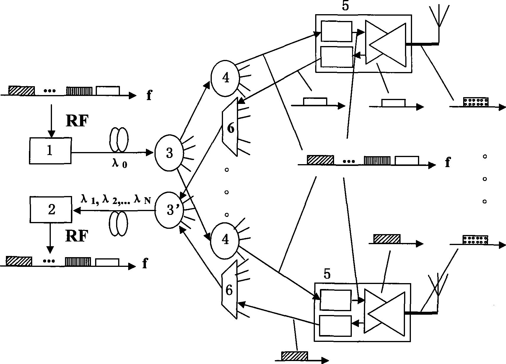
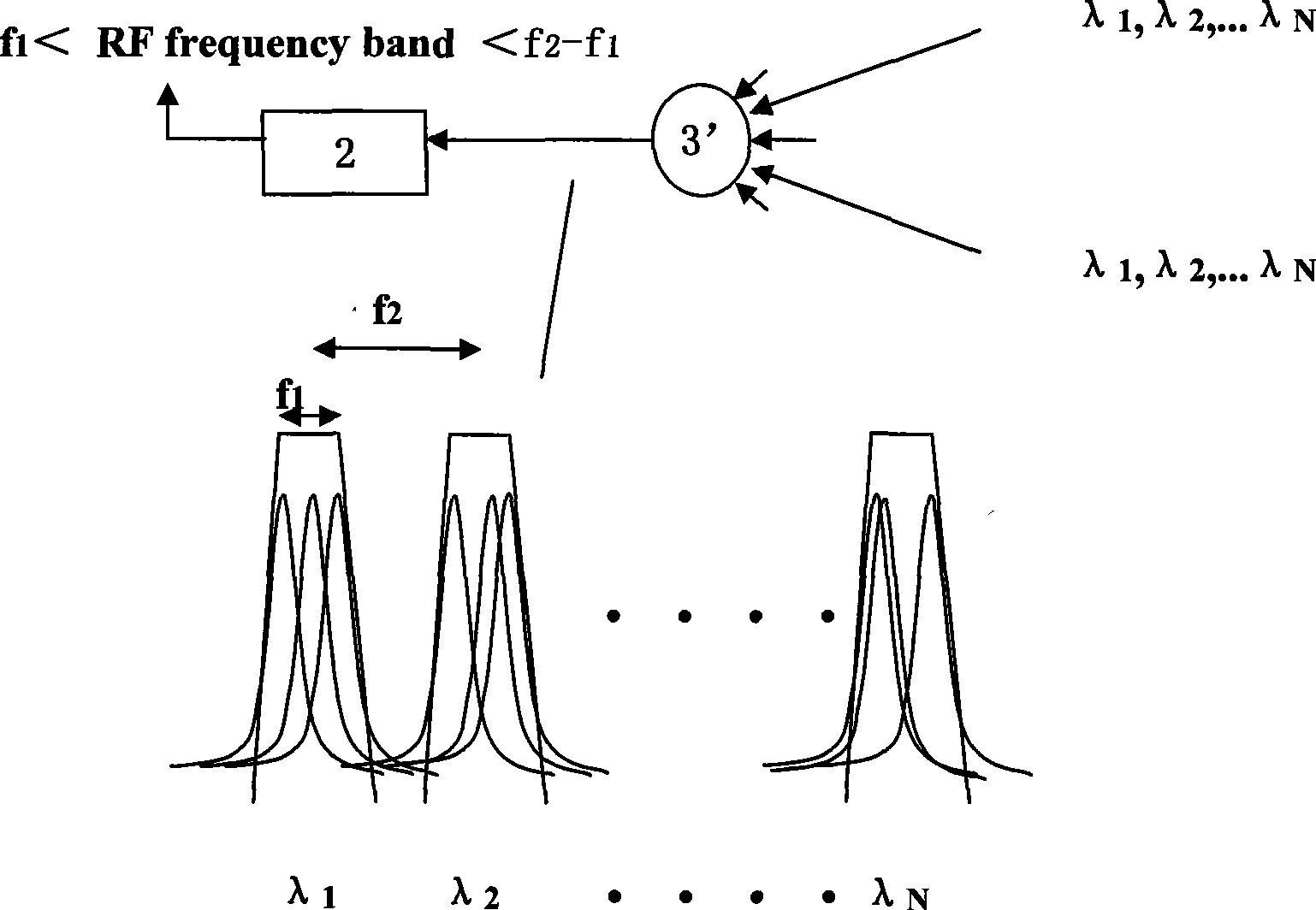
[0051] A kind of DAS scheme that the present invention proposes from the wireless base station control center (or calling the base station local end) to the indoor user antenna is to make full use of the broadband RF technology and the large bandwidth advantage of the optical transmitter / receiver, by adopting the passive optical network (PON) structure, the downlink is broadcast coverage mode; the uplink uses the WDMPON structure on the basis of the optical wavelength reuse method to solve the contradiction between the limited number of wavelengths and the large number of users. After the uplink multi-wavelength optical signal reaches the base station office With as few broadband optical receivers as possible, in the case of large-scale multi-point indo...


PUM


Abstract

The invention relates to a broadband wireless signal covering network based on a passive optical network structure. The network comprises a first fiber power divider / wave combiner, a plurality of user terminal units, an optical wavelength multiplexing / de-multiplexing device, a second fiber power divider / wave combiner and a broadband photoreceiver, wherein the first fiber power divider / wave combiner allocates light carrier signals of a light emitter to a plurality of fiber power dividers; a plurality of the user terminal units correspondingly receive the light carrier signals of the fiber power dividers, emit the light carrier signals to air and receive user uplink RF signals through antennas; the optical wavelength multiplexing / de-multiplexing device collects user uplink optical signals of a plurality of the user terminal units and transmits the signals to the uplink direction; the second fiber power divider / wave combiner collects the user uplink optical signals and transmits the signals to the uplink direction; and the broadband photoreceiver converts the received multi-wavelength user uplink optical signals into multi-bandwidth broadband RF signals and sends the signals to upper layer equipment. The broadband wireless signal covering network solves the problem of realizing broadband wireless communication for large-scale indoor multiuser, strengthens the adaptability to the horizontal dynamic change of uplink optical signal power and can adapt to the functional requirement of various wireless communication systems.

Description

technical field [0001] The invention relates to a broadband wireless signal coverage network. In particular, it relates to a broadband wireless signal coverage network based on a passive optical network structure suitable for large-scale and large-scale indoor broadband wireless signal coverage. Background technique [0002] With the popularization of 3G technology and the continuous development of 4G and millimeter wave technology, wireless technology has a tendency to further develop into high-frequency bands, and it is a way for multiple formats and multiple frequency band signals to coexist. Due to the large spatial attenuation of high-frequency signals and the limitation of cable transmission characteristics, especially in complex indoor environments, the transmission and coverage of broadband wireless signals have become increasingly prominent. Statistics show that most of the wireless signal transmission and reception occurs in the indoor environment. If the wireless...

Claims


Application Information

Patent Timeline
Patent Type & Authority Applications(China)
IPC IPC(8): H04W16/00H04W88/08
Inventor 傅焰峰刘青江山周宁邹奉庭江毅
Owner GUANGXUN SCI & TECH WUHAN
Learn More