Rack and production method thereof

一种制造方法、齿条的技术,应用在带有齿的元件、皮带/链条/齿轮、便携式提升装置等方向,能够解决不理想、制造成本上升等问题,达到易于精度、抑制加工负荷、加工负荷抑制的效果

Active Publication Date: 2009-09-30
NSK LTD
View PDF4 Cites 24 Cited by
  • Summary
  • Abstract
  • Description
  • Claims
  • Application Information

AI Technical Summary

Problems solved by technology

In any case, in order to limit the cross-sectional shape of the above-mentioned material to a predetermined shape, it is not preferable to perform the same processing as that for forming the above-mentioned concave portion, which will lead to an increase in manufacturing cost.

Method used


Image

  • Rack and production method thereof
  • Rack and production method thereof
  • Rack and production method thereof

Examples


Embodiment Construction

[0094] [First example of embodiment]

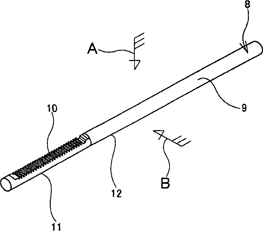
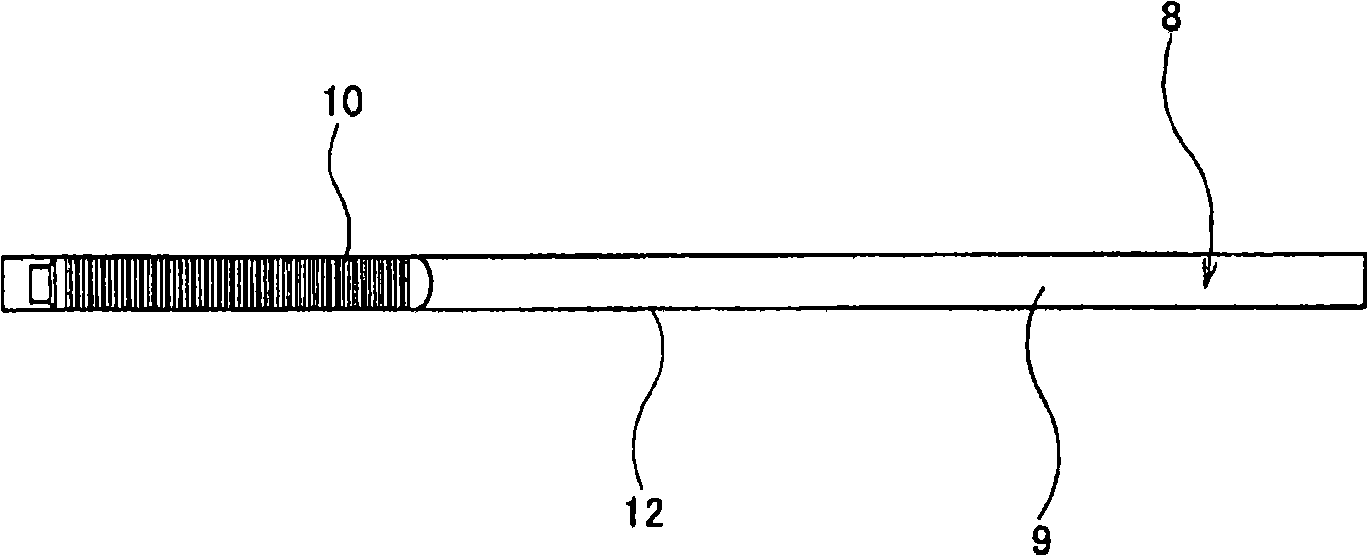
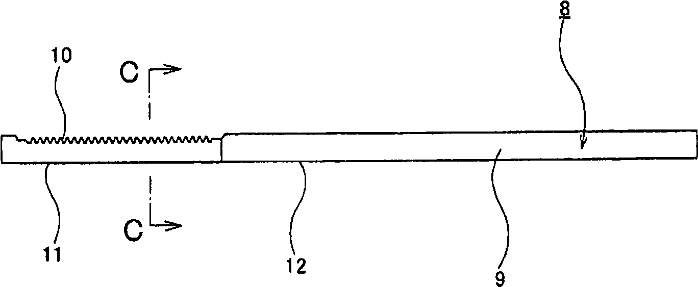
[0095] Figure 1~8 This shows the first example of the embodiment of the present invention. First, use Figure 1~4 The structure of the rack 8 of this example will be described. In addition, in the following description, the radius of curvature of each surface refers to the radius of curvature of the cross-sectional shape of each surface unless otherwise specified.

[0096] The rack 8 is made of a metal material such as carbon steel, stainless steel, etc., and has a rod 9 with a circular cross-section as a solid member, and a part of the rod 9 in the axial direction ( Figure 1~3 (Left part) of the rack teeth 10 formed by plastic working on the radial single side surface. In the case of this example, the above-mentioned rod portion 9 is integrally made of the same metal material from the outer peripheral surface to the center portion over the entire length. In addition, in a portion of the rod portion 9 in the axial direction, the radius of ...


PUM


Abstract

A light-weight structure capable of sufficiently ensuring any of the width size, strength and rigidity of a rack tooth (10), and a production method thereof. A rack tooth (10) is formed by plastic working on one side surface in the radial direction of a part in the axial direction of a sectionally circular rod unit (9). The radius of curvature of the section shape of a portion deviated in the circumferential direction from a rack-tooth (10) forming portion is set to be larger than the radius of curvature of the section shape of an outer circumferential surface of the remaining part in the axial direction of the rod unit (9). For this purpose, as shown by (A)->(B), the part in the axial direction and the remaining part in the circumferential direction are formed into a partially cylindrical surface portion (17) having a radius of curvature larger than that of the outer circumferential surface of a material (13) while a portion in the axial direction of the material (13) and a portion in the circumferential direction are being crushed, thereby defining an intermediate material (20).Then, as shown by (C)->(D), the above rack tooth (10) is formed at a portion in the axial direction ofthe intermediate material (20) and a portion in the circumferential direction. Finally, as shown by (E)->(F), it is subjected to sizing to complete a rack (8).

Description

Technical field [0001] The present invention relates to an improvement in a method of manufacturing a rack, which is assembled in a rack-and-pinion steering device, for example, in a steering device for imparting a steering angle to a steering wheel of a motor vehicle. Background technique [0002] As a mechanism for converting the rotational motion from the steering wheel to the linear motion that imparts the rudder angle, the rack-and-pinion steering device using the rack-and-pinion mechanism can be smaller and lighter, and has high rigidity to obtain good steering. Sense, so it is widely used. [0003] Figure 40 An example of such a rack and pinion steering device is shown. In this steering device, the operation of the steering shaft 2 that rotates with the operation of the steering wheel 1 is transmitted to the input shaft 6 of the steering gear assembly 5 through the universal joint 3 and the intermediate shaft 4. The steering gear assembly 5 has a pinion that is rotationa...

Claims


Application Information

Patent Timeline
Patent Type & Authority Applications(China)
IPC IPC(8): B21K1/06B21J5/02B21J5/08B21J5/12B21K1/76F16H55/26
CPCB21K1/767F16H55/26B21J5/12Y10T29/49472Y10T29/49467Y10T74/1967Y10T29/49474
Inventor 小林一登水岛勇贵广田浩太郎坪内启
Owner NSK LTD
Why Eureka
Try Eureka