Organic electroluminescence panel, organic electroluminescence display, organic electroluminescence illumination and method of manufacturing them
一种制造方法、电致发光元件的技术,应用在电致发光光源、照明装置、半导体/固态器件制造等方向,能够解决有机EL元件劣化等问题
- Summary
- Abstract
- Description
- Claims
- Application Information
AI Technical Summary
Problems solved by technology
Method used
Image
Examples
Embodiment approach 1
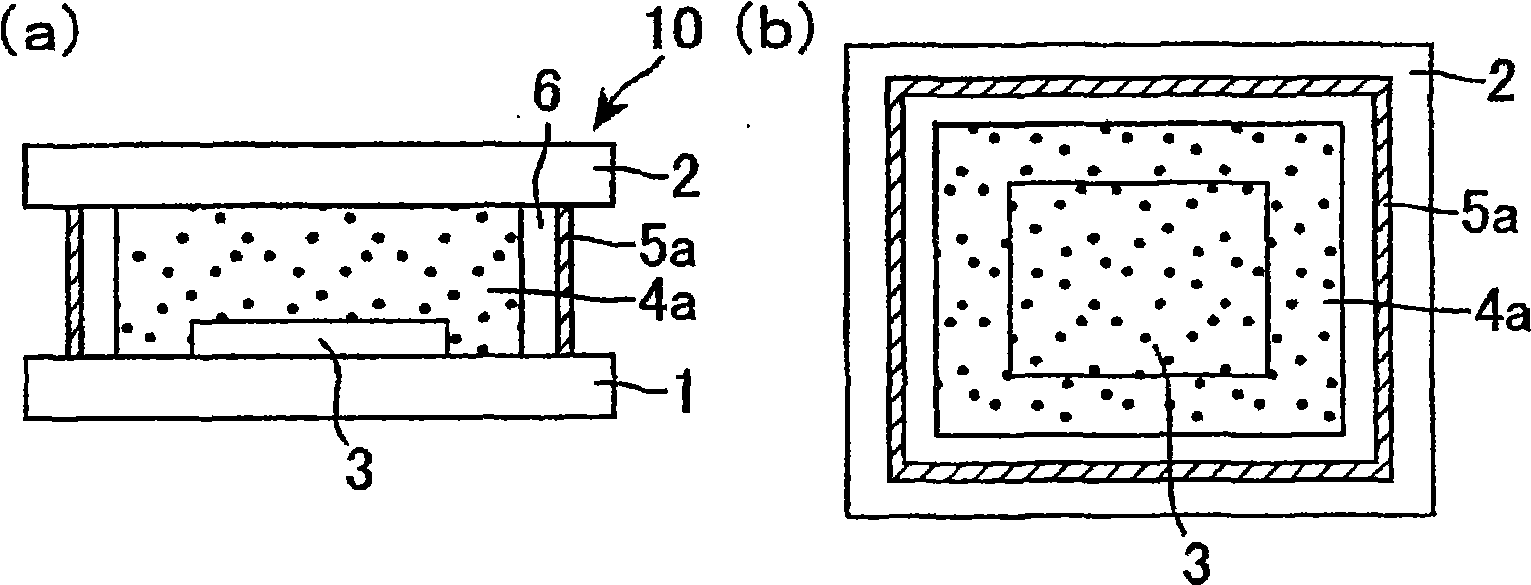
[0060] figure 1 (a) is a schematic cross-sectional view showing the structure of the organic EL panel of Embodiment 1, figure 1 (b) is a schematic plan view showing the structure of the organic EL panel of the first embodiment.
[0061] The organic EL panel 10 of Embodiment 1, such as figure 1 As shown in (a) and (b), it includes: a flat element glass (element substrate) 1; a flat plate sealing glass (sealing substrate) 2 opposite to the element glass 1; a sealing glass 2 disposed on the element glass 1- The organic EL element 3 on the side; the cured product (first sealing member) 5a of the liquid sealing material (airtight seal, liquid adhesive) that seals between the element glass 1 and the sealing glass 2; and the liquid sealing material The decompression or vacuum space 6 is formed between the cured products 5a, and the cured product (second sealing member) 4a of the solid sealing material covering the organic EL element 3 is bonded. exist figure 1 In (a) and (b),...
Embodiment approach 2
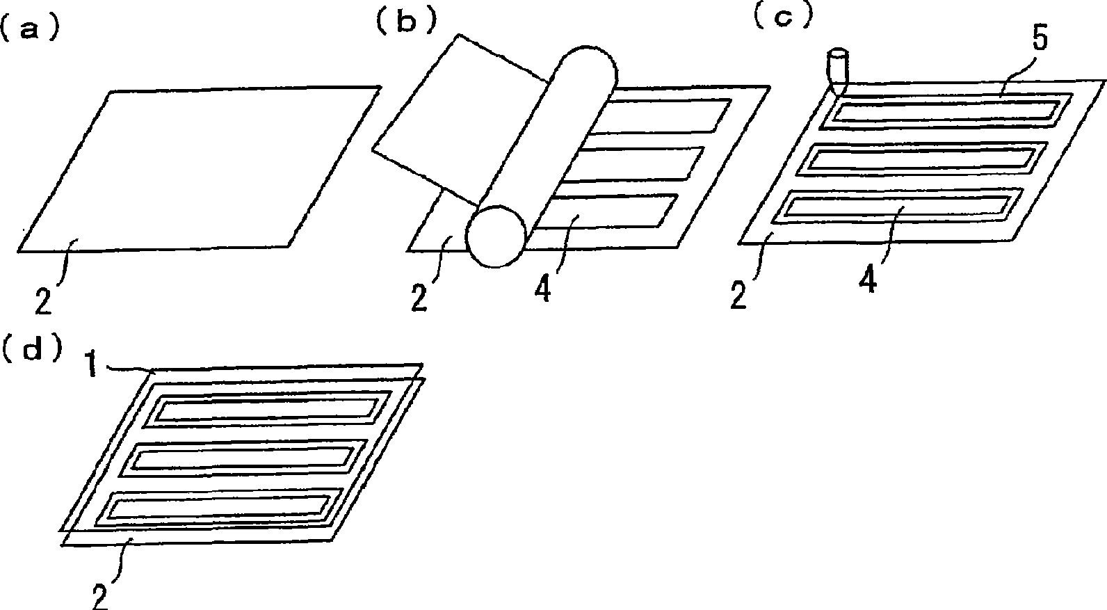
[0092] image 3 (a)-(d) are perspective schematic diagrams which show the manufacturing process of the organic electroluminescent panel of Embodiment 2.
[0093] First, if image 3 As shown in (a), a sealing glass (sealing substrate) 2 is prepared.
[0094] Next, although not shown, a plurality of organic EL elements are formed on the element glass (element substrate).
[0095] Next, using a roll-to-roll method such as image 3 As shown in (b), the solid sealing material 4 is pasted on the sealing glass 2 (solid sealing material arranging step). The solid sealing material 4 is attached to a position corresponding to the upper portion of the plurality of organic EL elements 3 when the sealing glass 2 and the element glass 1 are bonded together. By using the common solid sealing material 4 for a plurality of organic EL elements 3 in this way, compared with the case where the solid sealing material 4 is attached to each organic EL element 3, the tact time (tact time) required...
Embodiment approach 3
[0103] Figure 5 (a) is a schematic cross-sectional view showing a state where a liquid sealing material including a spacer is arranged on the element glass. Figure 5 (b) is expressed in Figure 5 (a) Later, the cross-sectional schematic diagram of the state when the element glass 1 and the sealing glass 2 are bonded together.
[0104] In this embodiment, if Figure 5 As shown in (a), after disposing the liquid sealing material 5 containing the spherical spacer 7 on the element glass 1, as shown in Figure 5 As shown in (b), it is the same as that of Embodiment 1 except that the element glass 1 and the sealing glass 2 are bonded together. The average particle diameter of the spacer 7 is preferably 1 to 100 μm, more preferably 20 μm or less in consideration of sealing performance and light transmittance. By including the spacer 7 in the liquid sealing material 5 in this way, the distance between the element glass 1 and the sealing glass 2 can be kept constant. Also, in th...
PUM
 Abstract
Description
Claims
Application Information
 - R&D
- Intellectual Property
- Life Sciences
- Materials
- Tech Scout
- Unparalleled Data Quality
- Higher Quality Content
- 60% Fewer Hallucinations
Browse by: Latest US Patents, China's latest patents, Technical Efficacy Thesaurus, Application Domain, Technology Topic, Popular Technical Reports.
© 2025 PatSnap. All rights reserved.Legal|Privacy policy|Modern Slavery Act Transparency Statement|Sitemap|About US| Contact US: help@patsnap.com


