
Metal vapor discharge lamp having configured envelope for stable luminous characteristics

Active Publication Date: 2006-07-18
PANASONIC CORP
View PDF6 Cites 0 Cited by
  • Summary
  • Abstract
  • Description
  • Claims
  • Application Information

AI Technical Summary

Benefits of technology

[0008]It is an object of the present invention to provide a metal vapor discharge lamp where a color temperature variation is small and a stable luminous characteristic is sustained even when the lamp is on for a long period of time, by attaining both inhibition of a liquid metal from flowing down into a gap between a center bulb and each of side tubes and sustainment of favorable metal vapor pressure.
[0011]The aforementioned configuration enables both inhibition of the light-emitting metal present in a liquid state from flowing down into the gap between the current supplier and each of the side tubes when the lamp is on or immediately after it is turned off, and sustainment of favorable metal vapor pressure, whereby it is possible to maintain a stable color temperature for a long period of time.

Problems solved by technology

When the light-emitting metal sinks into the gap, an amount of the light-emitting metal to contribute to luminescence in the discharge space is reduced, resulting in insufficient vapor pressure and a larger variation in color temperature.
Although increasing the amount of the light-emitting metal can be considered as a means to prevent the abovementioned problem, such an increase may promote the reaction of the light-emitting metal with the electrode or ceramic, deteriorating the life characteristic of the lamp.
However, in the case of shaping the boundary portion between the center bulb and each of the side tubes as described above, it becomes difficult to regulate the temperature of the boundary portion, raising a problem that favorable metal vapor pressure cannot be obtained.

Method used


Image

  • Metal vapor discharge lamp having configured envelope for stable luminous characteristics
  • Metal vapor discharge lamp having configured envelope for stable luminous characteristics
  • Metal vapor discharge lamp having configured envelope for stable luminous characteristics

Examples

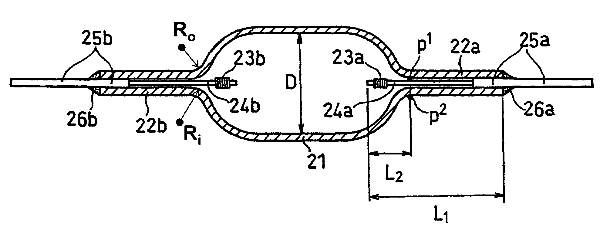
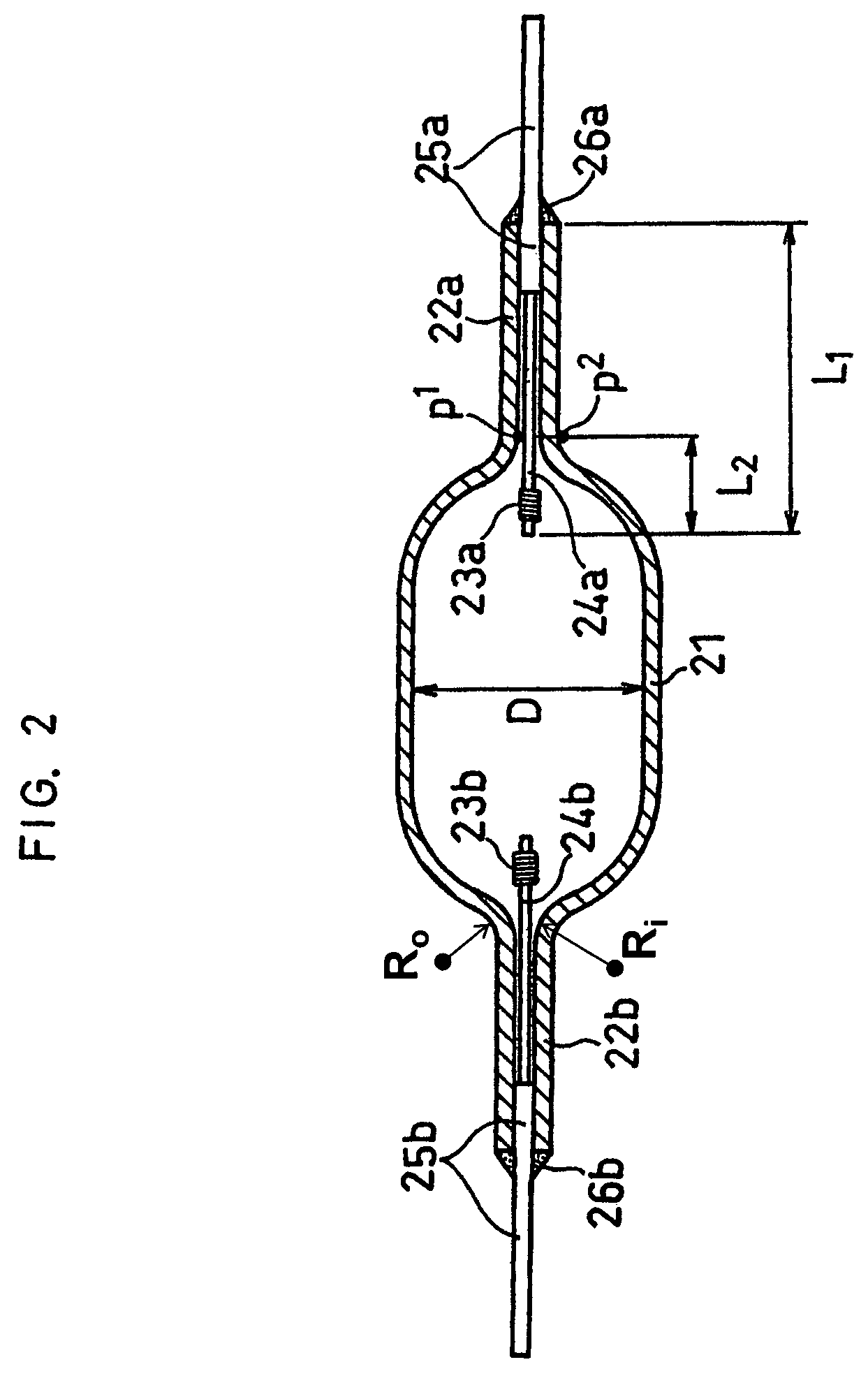

example 1

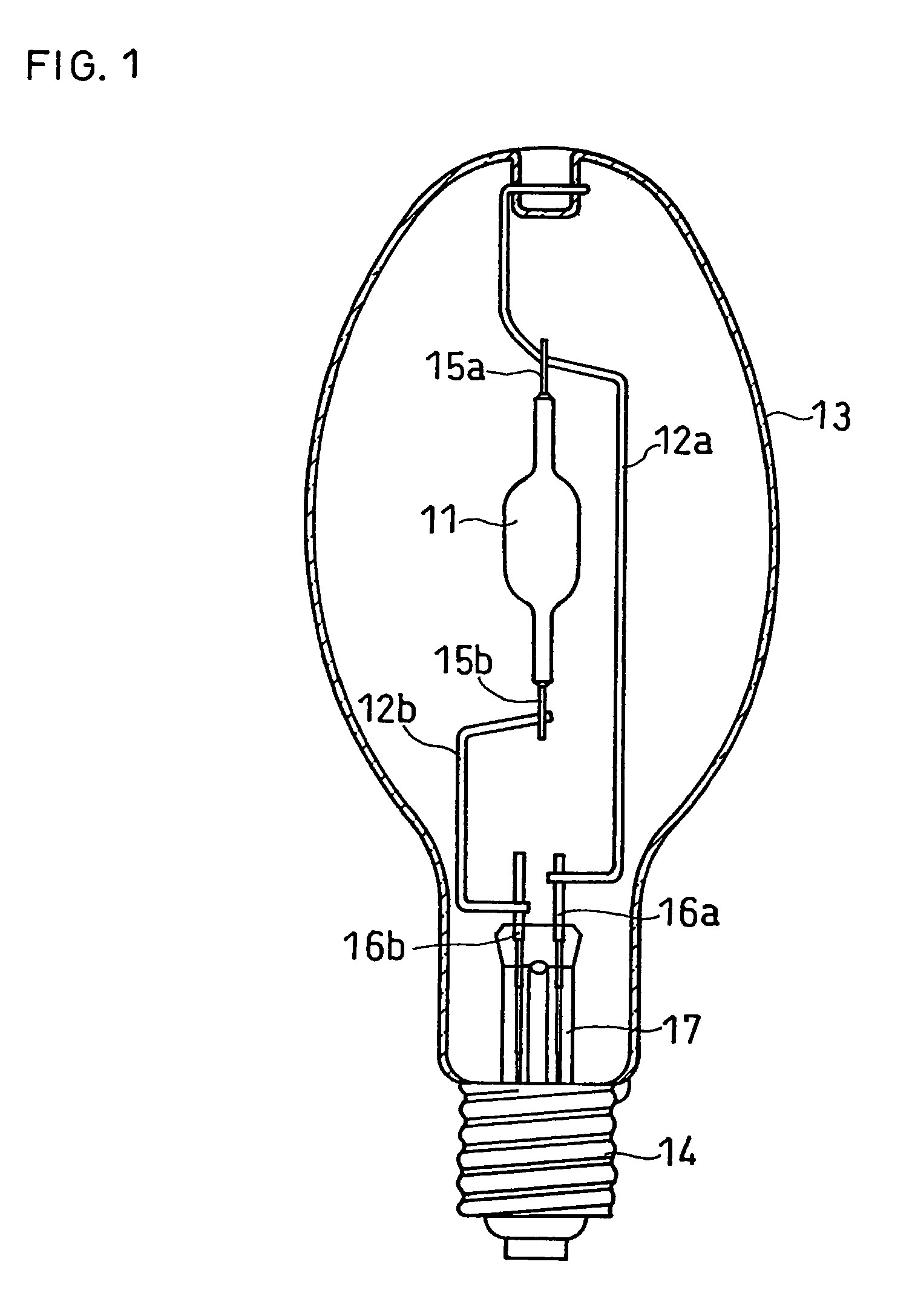
[0029]A luminous tube having an envelope made of alumina ceramic as shown in FIG. 2 was produced, and using this tube, a metal vapor discharge lamp as shown in FIG. 1, with an electric power of 200 W, was produced.

[0030]Herein, a ratio (Ri / D) of the smallest curvature radius Ri (mm) of the inner wall of the boundary portion between the center bulb and each of the side tubes to the inner diameter D (mm) of the center bulb in the envelope was varied as shown in Table 1.

[0031]The inner diameter D of the center bulb was 12.9 mm and the inner diameter of each of the side tubes was 1.3 mm.

[0032]In the discharge space enclosed as light-emitting metals were 0.9 mg of DyI3, 0.7 mg of HoI3, 0.9 mg of TmI3, 2.8 mg of NaI and 0.9 mg of TlI.

[0033]In the discharge space further enclosed were 310 hPa of argon as a noble gas and 29.2 mg of mercury.

[0034]As for pin portions of electrodes used were pins made of tungsten, having an outer diameter of 0.6 mm and a length of 12.5 mm.

[0035]As for lead-in ...

example 2

[0040]Except that the lamp electric power was changed from 200 W to 300 W, a metal vapor discharge lamp was produced and then evaluated in the same manner as in Example 1.

[0041]However, the inner diameter D of the center bulb was 17.1 mm and the inner diameter of each of the side tubes was 1.3 mm.

[0042]In the discharge space enclosed as light-emitting metals were 2.3 mg of DyI3, 1.9 mg of HoI3, 2.3 mg of TmI3, 6.7 mg of NaI and 2.3 mg of TlI.

[0043]In the discharge space further enclosed were 310 hPa of argon as the noble gas and 56.4 mg of mercury.

[0044]As for the pin portions of the electrodes used were pins made of tungsten, having an outer diameter of 0.7 mm and a length of 17.8 mm.

[0045]As for the lead-in wires used was conductive cermet (thermal expansion coefficient: 7.0×10⁻⁶) having an outer diameter of 1.2 mm and a length of 40 mm, obtained by mixing a molybdenum powder with an alumina powder, and then sintering the mixture.

[0046]As for the sealant used was glass frit made o...

example 3

[0050]Except that the lamp electric power was changed from 200 W to 150 W, a metal vapor discharge lamp was produced and then evaluated in the same manner as in Example 1.

[0051]However, the inner diameter D of the center bulb was 12.0 mm and the inner diameter of each of the side tubes was 0.8 mm.

[0052]In the discharge space enclosed as light-emitting metals were 0.8 mg of DyI3, 0.6 mg of HoI3, 0.8 mg of TmI3, 2.2 mg of NaI and 0.8 mg of TlI.

[0053]In the discharge space further enclosed were 150 hPa of argon as the noble gas and 9.0 mg of mercury.

[0054]As for the pin portions of the electrodes used were pins made of tungsten, having an outer diameter of 0.5 mm and a length of 13.5 mm.

[0055]As for the lead-in wires used was conductive cermet (thermal expansion coefficient: 7.0×10⁻⁶) having an outer diameter of 0.7 mm and a length of 20 mm, obtained by mixing a molybdenum powder with an alumina powder, and then sintering the mixture.

[0056]As for the sealant used was glass frit made of...


PUM


Abstract

A metal vapor discharge lamp, comprises: a translucent ceramic envelope, the envelope comprising a center bulb for defining a discharge space and side tubes, the center bulb and the side tubes being integrally molded; a pair of current suppliers extending through hollows of the side tubes respectively, each of the current suppliers comprising an electrode and a lead-in wire, a first end of the electrode being disposed in the discharge space, a second end of the electrode being connected with the lead-in wire; a sealant for hermetically sealing open ends of the side tubes; and a light-emitting metal contained in the discharge space. An inner wall and an external wall of a seamless boundary portion between the center bulb and each of the side tubes have the smallest curvature radius of Ri mm and Ro mm, respectively. The center bulb has an inner diameter of D mm. The lamp has an electric power of P watts. The radius Ri, radius Ro, diameter D and electric power P satisfy,−0.00076P+0.304≦Ri / D≦−0.00076P+0.490,   Formula (1)where P≦350 watts; and1.28Ro≦Ri≦1.39Ro.   Formula (2)

Description

BACKGROUND OF THE INVENTION[0001]With regard to envelopes of metal vapor discharge lamps, envelopes made of translucent ceramic such as alumina ceramic have become increasingly common these days in place of conventional quartz glass. Translucent ceramic is more excellent in heat resistance than quartz glass and suitable for envelopes of high pressure discharge lamps, such as metal vapor discharge lamps, whose temperature becomes high when the lamps are on. For example, alumina ceramic has lower reactivity with light-emitting metals to be enclosed in an envelope than quartz glass, and it can thus be expected to prolong the life of metal vapor discharge lamps.[0002]A typical envelope of a metal vapor discharge lamp comprises: a center bulb for defining a discharge space and a pair of side tubes being extended from both ends of the center bulb. The side tubes have outer diameters smaller than that of the center bulb. Current suppliers are extending through hollows of the side tubes res...

Claims


Application Information

Patent Timeline
IPC IPC(8): H01J61/30H01J61/36H01J17/16H01J61/073H01J61/72
CPCH01J61/72H01J61/30
Inventor MIURA, MIKIOKAKISAKA, SHUNSUKENISHIURA, YOSHIHARU
Owner PANASONIC CORP
Learn More