

Corrugated steel ventral shield preflex composite beam and construction method thereof
A corrugated steel web, composite beam technology, applied in bridges, bridge materials, bridge construction and other directions, can solve the problems of complex construction technology, high cost of single-span pre-bent composite beams, lack of design, construction specifications and standards, etc. Easy construction, improved prestress loss, high prestress efficiency
- Summary
- Abstract
- Description
- Claims
- Application Information
AI Technical Summary
Problems solved by technology
Method used
Image

Examples
Embodiment 1
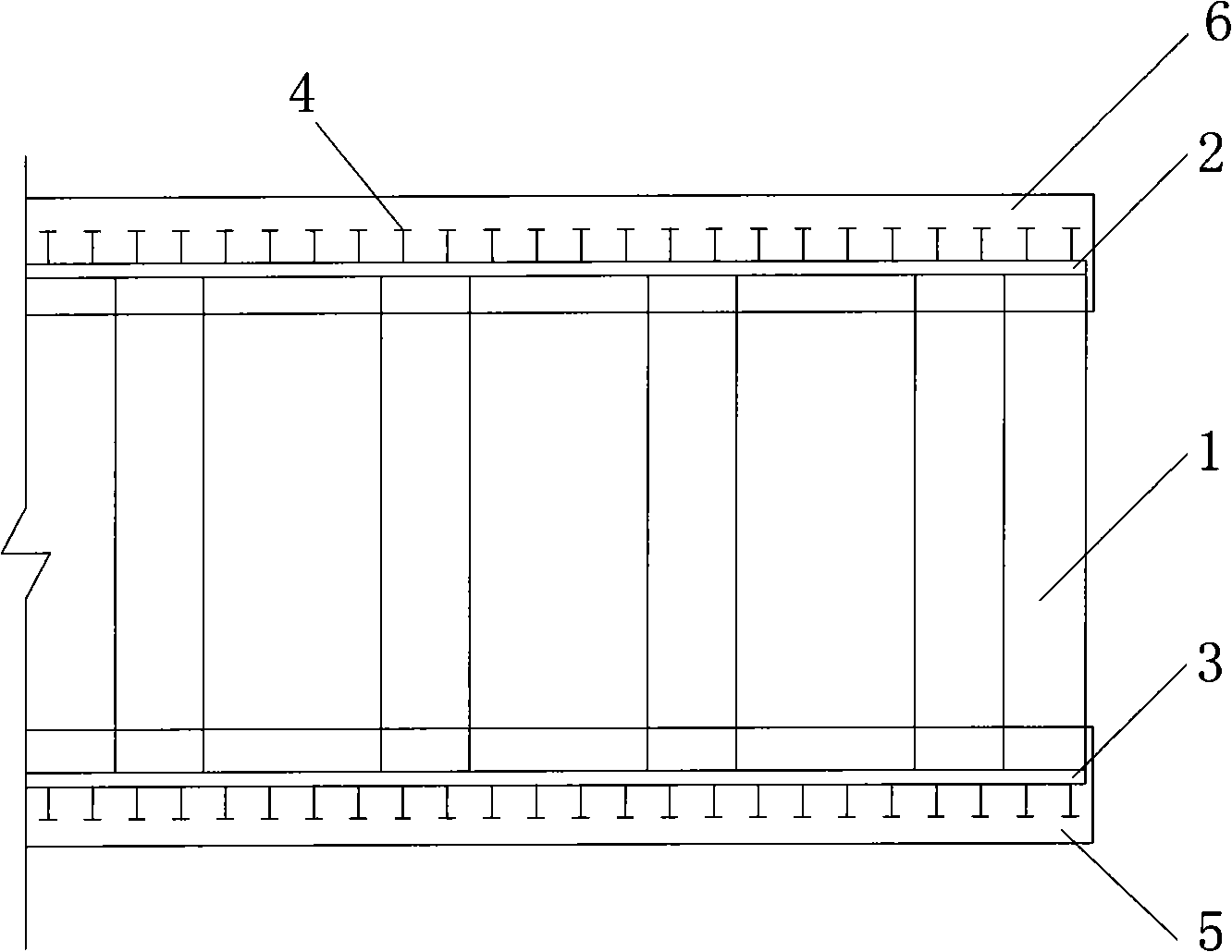
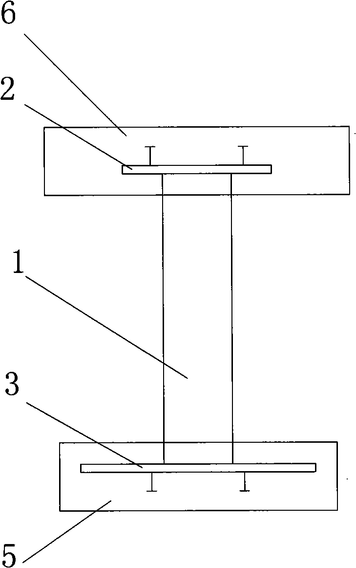
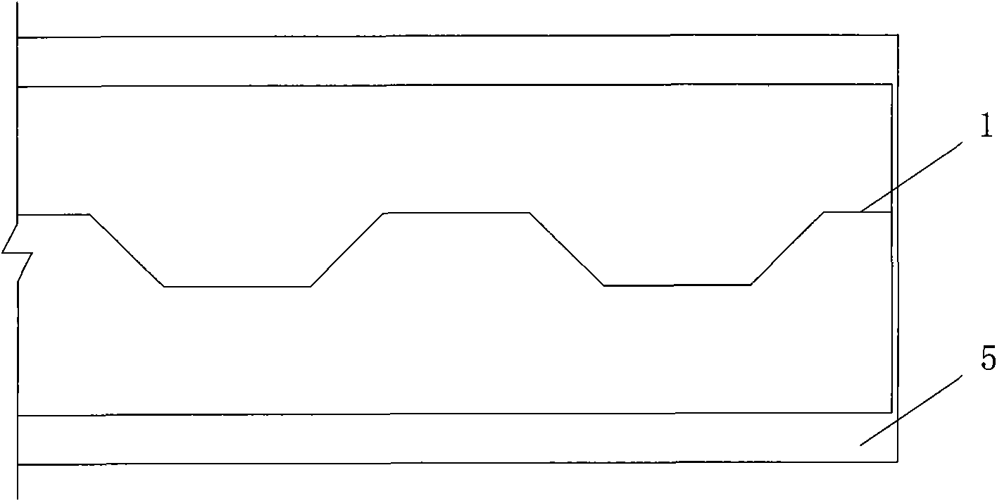
[0030] Embodiment 1: A corrugated steel web pre-bent composite beam, including the first-stage concrete 5 poured on the lower flange steel plate 3, the upper flange steel plate 2 connected with the second-stage concrete 6, and also includes a corrugated steel web 1, corrugated The steel web 1 is arranged between the lower flange steel plate 3 and the upper flange steel plate 2, and the three form an I-beam structure.
[0031] In the pre-bent composite beam with corrugated steel web according to the present invention, the second-stage concrete 6 is poured on the upper flange steel plate 2 .
[0032] In the pre-bent composite beam with corrugated steel web according to the present invention, the second-stage concrete 6 is connected with six end faces of the upper flange steel plate 2 . The connection of the six end faces can be understood as the second-stage concrete 6 wrapping the upper flange steel plate 2 .
[0033] In the erection process, if the second-stage concrete 6 is ...
Embodiment 2
[0045] Embodiment 2: A corrugated steel web pre-bent composite beam, including the first-stage concrete 5 poured on the lower flange steel plate 3, the second-stage concrete 6 connected to the upper flange steel plate 2, and also includes the corrugated steel web 1, corrugated The steel web 1 is arranged between the first-stage concrete 5 poured on the lower flange steel plate 3 and the second-stage concrete 6 connected to the upper flange steel plate 2, and the three form an I-beam structure.
[0046] In the pre-bent composite beam with corrugated steel web according to the present invention, the second-stage concrete 6 is poured on the upper flange steel plate 2 .
[0047]In a pre-bent composite beam with corrugated steel webs according to the present invention, the second-stage concrete 6 is connected to the upper end surface of the upper flange steel plate 2, and the second-stage concrete 6 is used not to wrap the upper flange steel plate 2, but only to be connected to the ...
PUM
 Abstract
Description
Claims
Application Information