A microstrip array antenna

A microstrip array and antenna technology, applied in the directions of antennas, antenna arrays, electrical components, etc., can solve the problems of difficulty in suppressing side lobes of ETC array antennas, and achieve the purpose of reducing the volume, suppressing the side lobe level, and improving the main lobe gain. Effect

Inactive Publication Date: 2009-10-07
BEIJING WATCH DATA SYST
View PDF0 Cites 28 Cited by
  • Summary
  • Abstract
  • Description
  • Claims
  • Application Information

AI Technical Summary

Problems solved by technology

[0005] The invention provides a microstrip array antenna, which can so...

Method used


Image

  • A microstrip array antenna
  • A microstrip array antenna
  • A microstrip array antenna

Examples


Embodiment Construction

[0017] A microstrip array antenna according to an embodiment of the present invention will be described in detail below with reference to the accompanying drawings.

[0018] It should be clear that the described embodiments are only some of the embodiments of the present invention, not all of them. Based on the embodiments of the present invention, all other embodiments obtained by persons of ordinary skill in the art without creative efforts fall within the protection scope of the present invention.

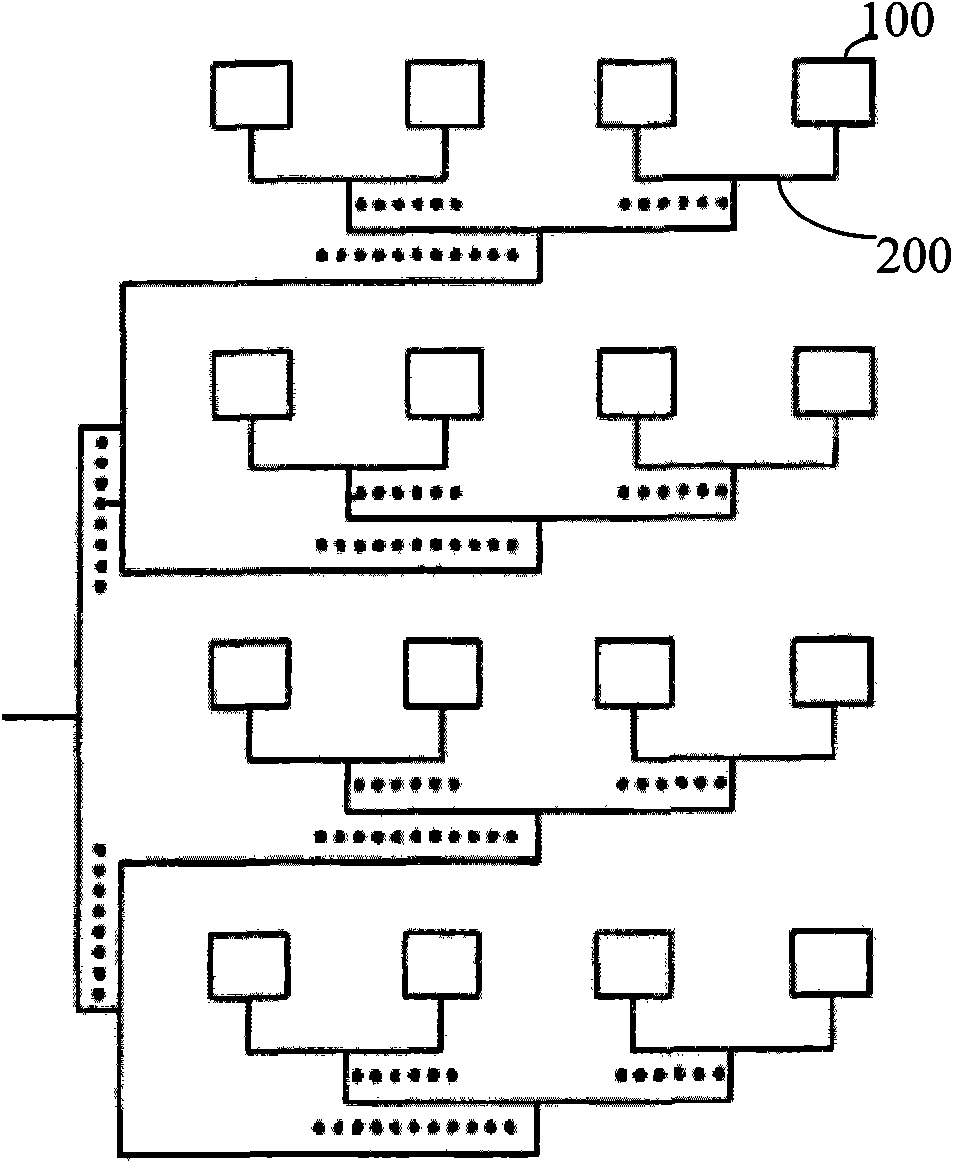
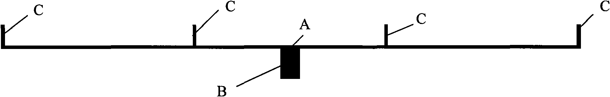
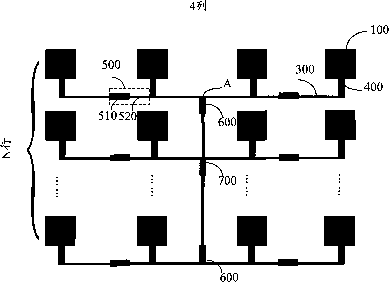
[0019] An embodiment of the present invention is a microstrip array antenna, including an antenna matrix composed of more than two antenna elements, the same row of the antenna matrix includes more than two antenna elements, located in the same row of antenna elements, each The antenna array elements are correspondingly connected to each output port of a multi-channel power divider, and cascaded impedance transformation sections are connected between adjacent antenna array eleme...


PUM


Abstract

The invention discloses a microstrip array antenna and relates to an antenna capable of resolving problem of low main lobe gain and difficult side-lobe suppression of ETC array antenna. The microstrip array antenna includes a antenna array composed of more than two antenna array elements, the antenna matrix includes more than two antenna array elements in the same row with each the antenna array element connecting with each output terminal port of one multiplex power divider, and between the adjacent antenna array elements, that are in different distance from the central line of the antenna matrix, is connected by cascaded impedance transforming section. The invention is suitable for antennas in ETC system.

Description

technical field [0001] The invention relates to an antenna, in particular to a microstrip array antenna. Background technique [0002] The electronic toll collection system (ETC system for short) can use the automatic vehicle identification technology to complete the two-way communication between the roadside unit (Roadside Unit, RSU) and the on-board unit (On BoardUnit, OBU), and collect the charging data through the computer network. processing to realize full electronic toll collection without parking. Non-stop toll collection technology is especially suitable for use in highways or bridge-tunnel environments with heavy traffic. The implementation of non-stop charging can allow vehicles to pass at high speeds, greatly improving the traffic capacity of the highway. [0003] The RSU of the non-stop charging system is generally erected on the gantry of the toll booth. The vehicle equipped with the OBU passes through the toll booth at a speed greater than 20 km / h, and both ...

Claims


Application Information

Patent Timeline
IPC IPC(8): H01Q13/08H01Q21/00
Inventor 肖春来
Owner BEIJING WATCH DATA SYST
Why Eureka
Try Eureka