Device for automatically testing optical waveguide devices in batches

An automatic test device and optical waveguide technology, applied in the direction of testing optical performance, etc., can solve the problems of poor comparability, unstable data, time-consuming and labor-intensive, etc., to meet the test requirements, improve measurement efficiency, and ensure consistency.

Inactive Publication Date: 2009-10-14
ZHEJIANG UNIV
View PDF0 Cites 6 Cited by
  • Summary
  • Abstract
  • Description
  • Claims
  • Application Information

AI Technical Summary

Problems solved by technology

[0004] The purpose of the present invention is to provide a device for batch automatic testing of optical waveguide devices for the shortcomings of time-consuming and labor-intensive testing of optical waveguide devices one by one and in some time-consuming test items, the data is unstable and poor comparability

Method used


Image

  • Device for automatically testing optical waveguide devices in batches
  • Device for automatically testing optical waveguide devices in batches
  • Device for automatically testing optical waveguide devices in batches

Examples


Embodiment

[0026] The serial test is basically similar to ordinary manual operation, and only uses automatic control to realize optical path conversion, which improves the test efficiency.

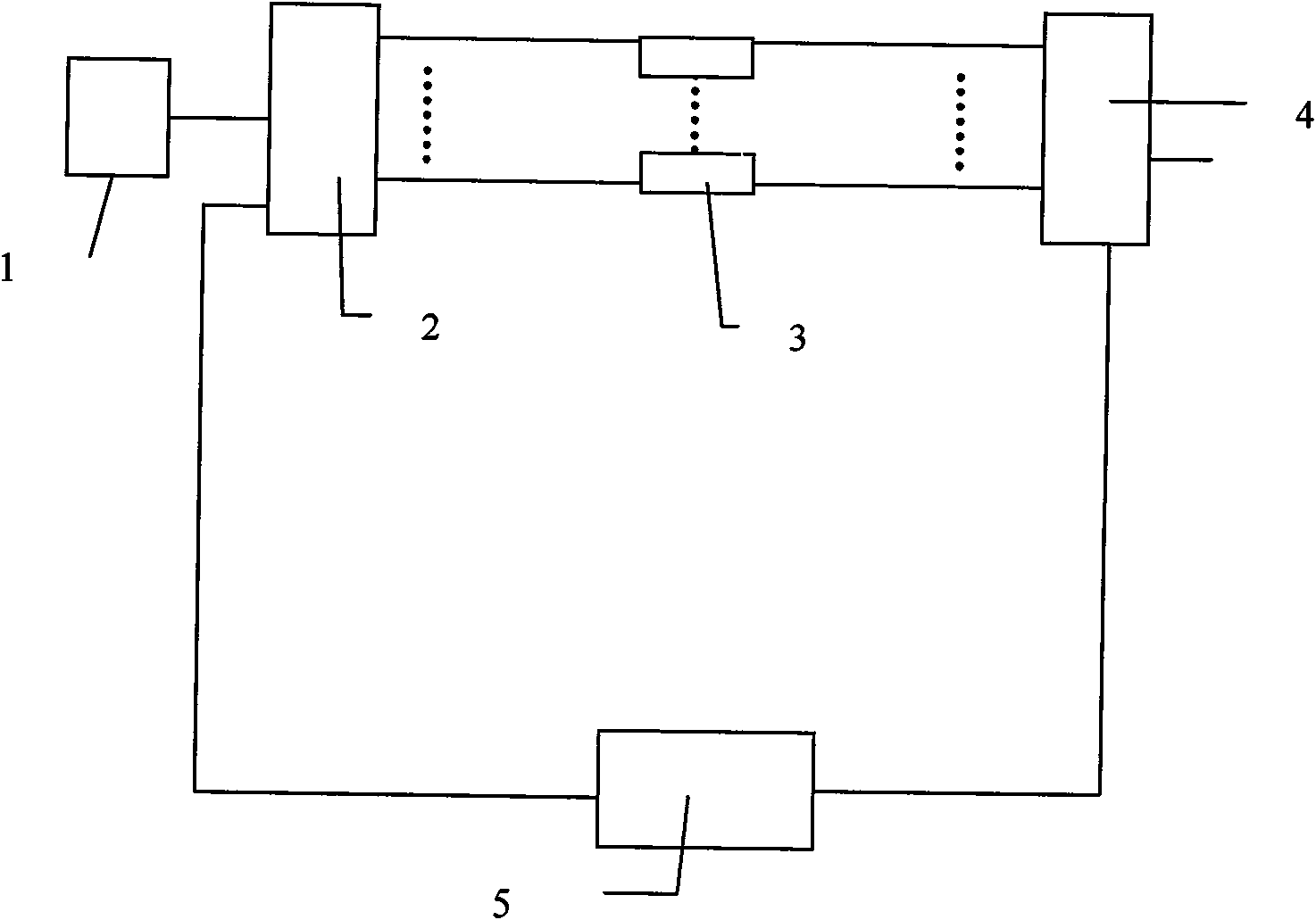
[0027] Taking the experiment of evaluating fiber rings at different temperatures as an example, this experiment needs to obtain performance data of fiber rings at low temperature, room temperature and high temperature. The experimental process is as follows: the light emitted by the SLD light source 5-1 enters the fiber ring 5-6 through the beam splitter 5-2, the Y waveguide 5-3 and the first optical path switching system 5-4, and then passes through the second optical path switching system 5- 7 Returning to the Y waveguide, the optical signal passing through the beam splitter is collected by the PIN tube 5-8, read by the lock-in amplifier 5-9, and finally processed by the data processing system.

[0028] If the circuit is manually switched and each device is tested individually, it takes time (about...


PUM


Abstract

The invention discloses a device for automatically testing optical waveguide devices in batches. In the device, the first input end of a first optical path switching system is connected with a laser source through optical fiber; the output end of the first optical path switching system is connected with the input end of a test system through optical fiber; the first input end of a second optical path switching system is connected with the output end of the test system through optical fiber; and a stepper motor controller is respectively connected with the second input end of the first optical path switching system and the second input end of the second optical path switching system through signal wires. Compared with the prior art, the device reduces the complexity of manual operation and improves the measuring efficiency, synchronously ensures the relative uniformity of the test environment and avoids the extra loss caused by manually switching the optical paths; and the invention provides a plurality of test modes, thus being capable of meeting different test requirements.

Description

technical field [0001] The invention relates to a testing device for an optical waveguide device, in particular to a batch automatic testing device for an optical waveguide device. Background technique [0002] In the testing of a large number of optical waveguide devices, a single test one by one not only needs to rebuild the system, but also the test environment is not easy to maintain consistency, resulting in time-consuming, laborious and inaccurate test results. [0003] The batch testing of electronic components has been studied relatively well, and the equipment and devices have also been used in various industrial production occasions. Compared with the batch testing of electronic components, the method of batch testing of optical waveguide devices is still immature. How to conduct batch testing of optical waveguide devices to save time and effort, and at the same time meet the needs of mass testing has become an urgent problem to be solved. The traditional manual ...

Claims


Application Information

Patent Timeline
Patent Type & Authority Applications(China)
IPC IPC(8): G01M11/02
Inventor 王冬云马妍舒晓武刘承
Owner ZHEJIANG UNIV
Why Eureka
Try Eureka