
Auxiliary cooler for truck cap and a vehicle provided with a cooling member

A cooling component and auxiliary cooling technology, applied in the field of vehicles, can solve the problem of occupying extra space

Inactive Publication Date: 2009-10-14
VOLVO LASTVAGNAR AB
View PDF3 Cites 2 Cited by
  • Summary
  • Abstract
  • Description
  • Claims
  • Application Information

AI Technical Summary

Problems solved by technology

A limitation of existing technologies that provide additional cooling is the need for deflectors, which take up additional space, which may be undesirable

Method used


Image

  • Auxiliary cooler for truck cap and a vehicle provided with a cooling member
  • Auxiliary cooler for truck cap and a vehicle provided with a cooling member
  • Auxiliary cooler for truck cap and a vehicle provided with a cooling member

Examples


Embodiment Construction

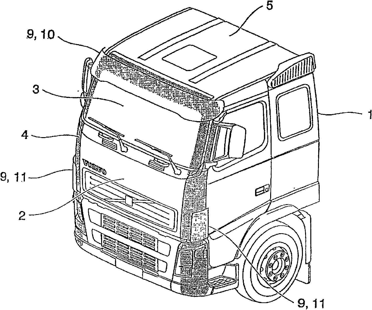
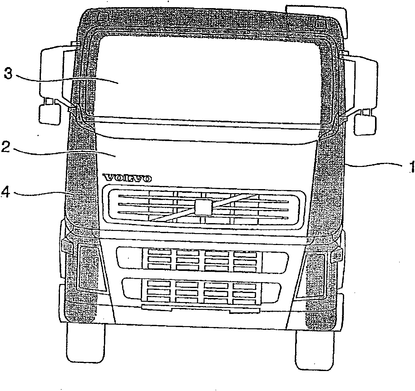
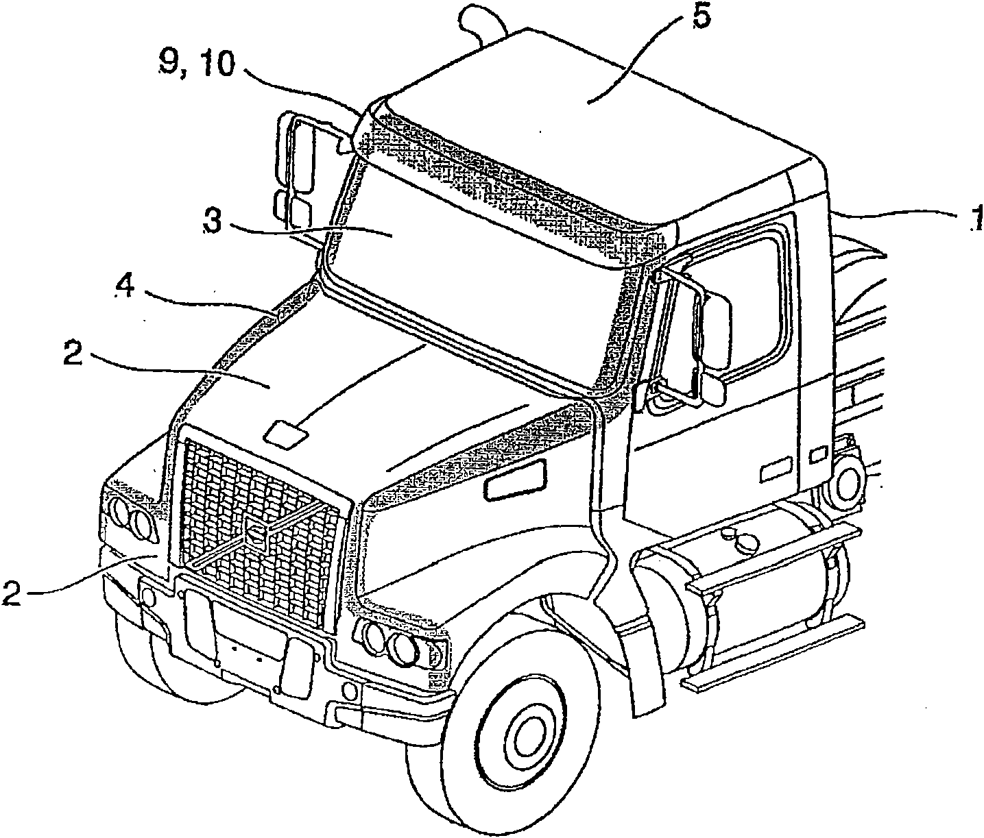
[0029] refer to Figures 1 to 3 , shows the cabin 1 , the front side 2 , the windshield 3 , the edge area 4 and the roof 5 of the vehicle. figure 1 Shown are the components for the nose cab, while the image 3 The same components on the long-head cab are shown. Furthermore, examples of external panels 9 as sun visors 10 and dust deflectors 11 are shown.

[0030] Figure 4 and Figure 5 An example of the configuration of the cooling member 6 applied within the present invention is shown. The cooling member is defined as an outline box enclosing one or more cooling elements 7 useful in the present invention, it being understood that the cooling elements need not extend from one side of the cooling member to the other. The cooling element 7 may be a heat sink constructed according to methods known in the prior art, for example to make the direction of the air flow more or less constant as it passes through the heat sink, or to change the air flow to some extent. The latter ...


PUM


Abstract

The invention discloses a vehicle, such as a heavy vehicle, e.g. a truck, comprising a cabin (1) having a front side (2) including a windshield (3) and edge regions (4), a roof (5), and driving means including a cooling system, where said vehicle is provided with at least one auxiliary cooling member (6) comprising at least one cooling element (7), and an air intake (8), where at least a part of the cooling member is protruding from the front side (2) to utilize at least a part of the general airflow running substantially parallel with the front side (2) when the vehicle is moving forward. In a preferred embodiment, at least one exterior panel (9) is mounted to cover the cooling elements (7) of the cooling member (6), and it is preferred that this exterior panel (9) is a sun visor (10) or dirt deflector (11). Hereby, there is achieved significant additional cooling without altering the overall appearance and design of the truck and thus also keeping within the size requirements of the vehicle.

Description

technical field [0001] The invention relates to a vehicle, such as a heavy vehicle, for example a truck, comprising a cab with a front side comprising a windshield and edge regions and a roof, and a drive comprising a cooling system. Background technique [0002] Most cars and trucks cool the engine through the front air intake, usually in the form of a grille, combined with a large radiator placed immediately behind the grille. Typically liquid cooling is used such that the radiator is connected to fluid passages running along the cylinder block, allowing heat energy exchange with the engine. [0003] Efforts to add additional cooling capacity are known from JP61150823, where an additional radiator is mounted in a spoiler on the roof of the truck cab. A similar design is known from DE3916692 in which an additional radiator is positioned behind a deflector formed by a plurality of flaps. The relative distance between these fins can then be adjusted to allow air to pass thr...

Claims


Application Information

Patent Timeline
Patent Type & Authority Applications(China)
IPC IPC(8): B60K11/04B62D35/00
CPCB62D35/001B60Y2200/14B62D33/06B60K11/04
Inventor 埃里克·达尔伦纳特·埃里克松
Owner VOLVO LASTVAGNAR AB
Learn More