Multifunction rotavator, speed change gear box thereof capable of reversing easily and extending shaft thereof

The technology of a variable speed gearbox and a rotary tiller is applied in the fields of farming equipment, agricultural machinery and equipment, and application, etc., and can solve the problems of time-consuming and laborious disassembly and assembly, inconvenient adjustment and maintenance, and burying straw into the soil, etc., and achieves simple structure and low cost. Low, easy to disassemble

Inactive Publication Date: 2009-10-21
葛玉明
View PDF0 Cites 0 Cited by
  • Summary
  • Abstract
  • Description
  • Claims
  • Application Information

AI Technical Summary

Problems solved by technology

[0003] The main disadvantage of this type of rotary tiller is that it has a single function and can only be used in farmland with relatively little straw. For fields with a lot of straw left on the surface after harvesting crops such as wheat and rice, the straw cannot be buried in the soil during rotary tillage. , farmers need to purchase additional reverse stubble burying machines, and also purchase ditching machines when ditching is required
Therefore, farmers need to purchase three agricultural machines with different purposes, which is not only costly, but also often needs to be replaced with supporting agricultural machines with different functions due to different purposes when working in the farmland, which is time-consuming and laborious in the disassembly and assembly process with the tractor; The gear box of the machine is a whole, it is troublesome to disassemble and assemble, and it is not easy to adjust and maintain

Method used


Image

  • Multifunction rotavator, speed change gear box thereof capable of reversing easily and extending shaft thereof
  • Multifunction rotavator, speed change gear box thereof capable of reversing easily and extending shaft thereof
  • Multifunction rotavator, speed change gear box thereof capable of reversing easily and extending shaft thereof

Examples


Embodiment 1

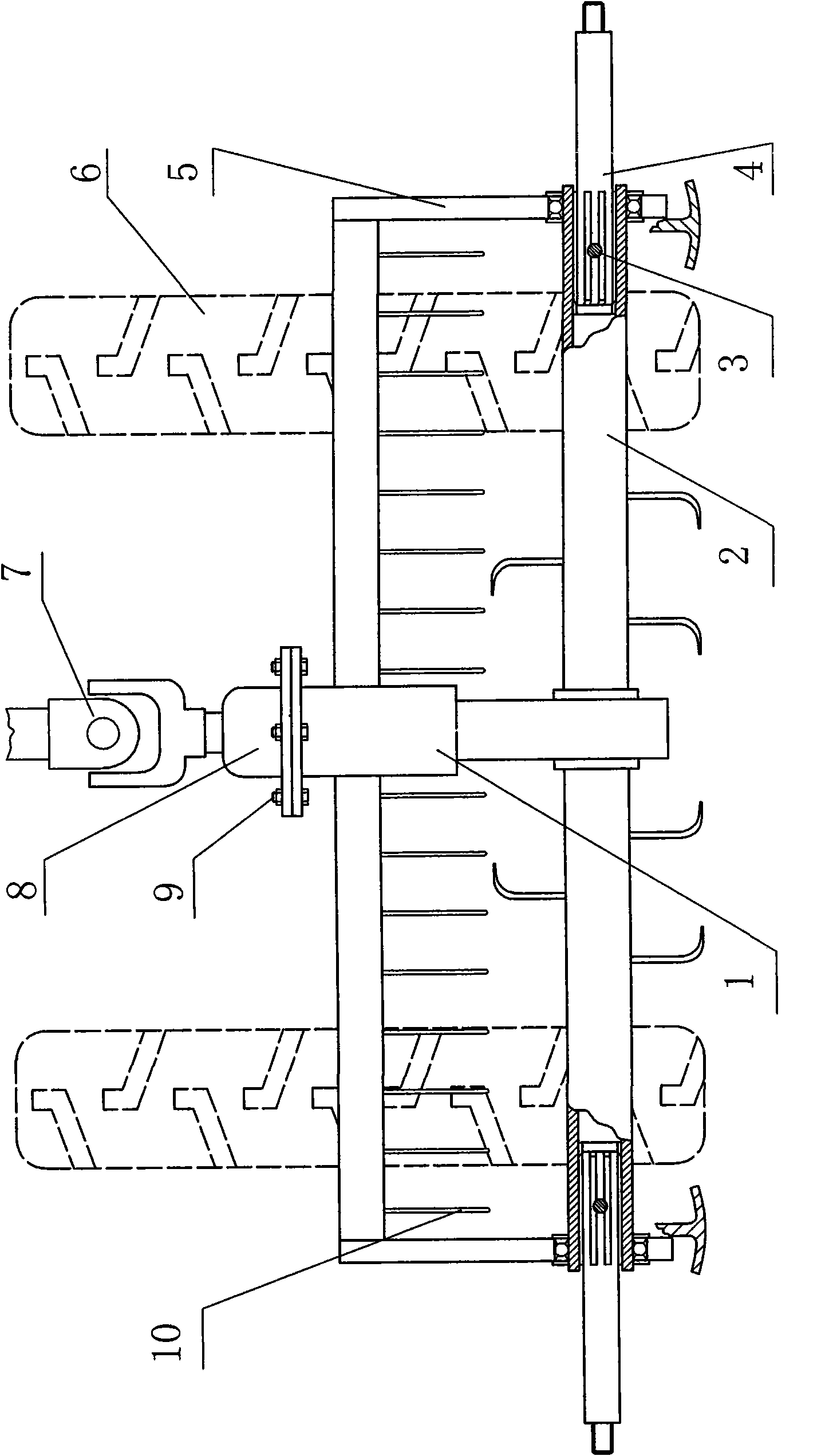
[0041] Embodiment 1, the multifunctional rotary tiller of the present invention, figure 1 It is the structure of Embodiment 1 shown from the rear view direction of the tractor: figure 1 Middle: 1. Gear box lower housing, 2. Coulter shaft, 3. Locking pin, 4. Extension shaft, 5. Rotary cultivator frame, 6. Tractor drive wheel, 7. Universal joint, 8. Gear Case upper shell, 9, connecting bolts, 10, stubble fence. figure 1 The middle coulter shaft 2 is a circular tube structure, the inner walls of both ends are provided with internal splines, the extension shaft 4 is inserted into the coulter shaft 2, and its section is an external spline corresponding to the inner wall of the coulter shaft 2 tube , and use the locking pin 3 to position the two for torque transmission. The cross-sectional shape of the elongated shaft 4 and the tubular coulter shaft 2 can also be polygonal, square or directly cylindrical, and the locking pin 3 is axially positioned to transmit the torque, and the ...

Embodiment 2

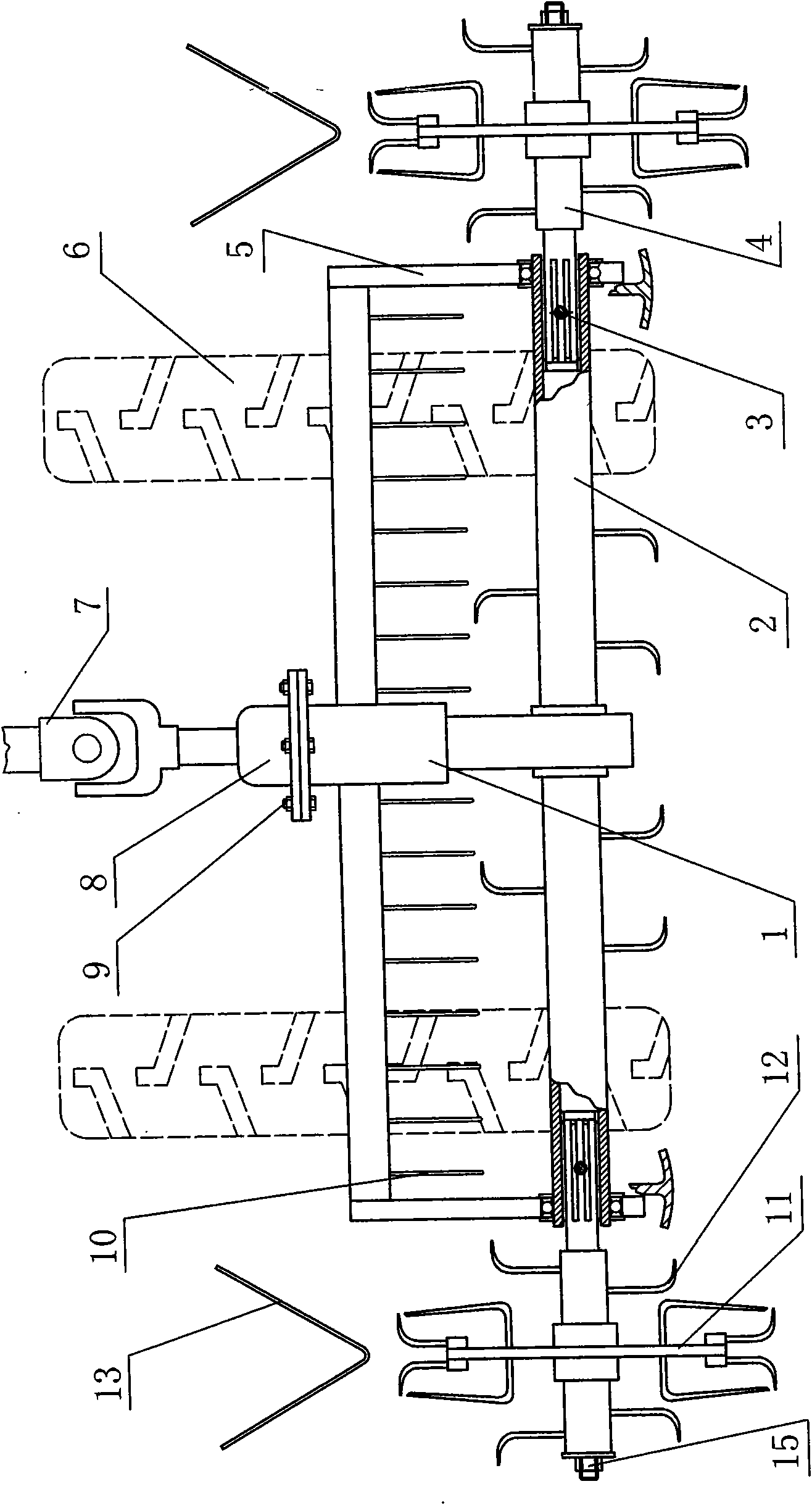
[0043] Embodiment 2, the multifunctional rotary cultivator of assembling ditching cutter head, figure 2 It is the structure of Embodiment 2 of assembling the ditching cutter head on the extension shaft 4 shown from the rear view direction of the tractor, figure 2 Middle: 1. Gear box lower housing, 2. Coulter shaft, 3. Locking pin, 4. Extension shaft, 5. Rotary cultivator frame, 6. Tractor drive wheel, 7. Universal joint, 8. Gear Case upper casing, 9, connecting bolts, 10, stubble fence, 11, ditching cutter head, 12, rotary tiller, 13, soil dividing plate, 15 nuts.

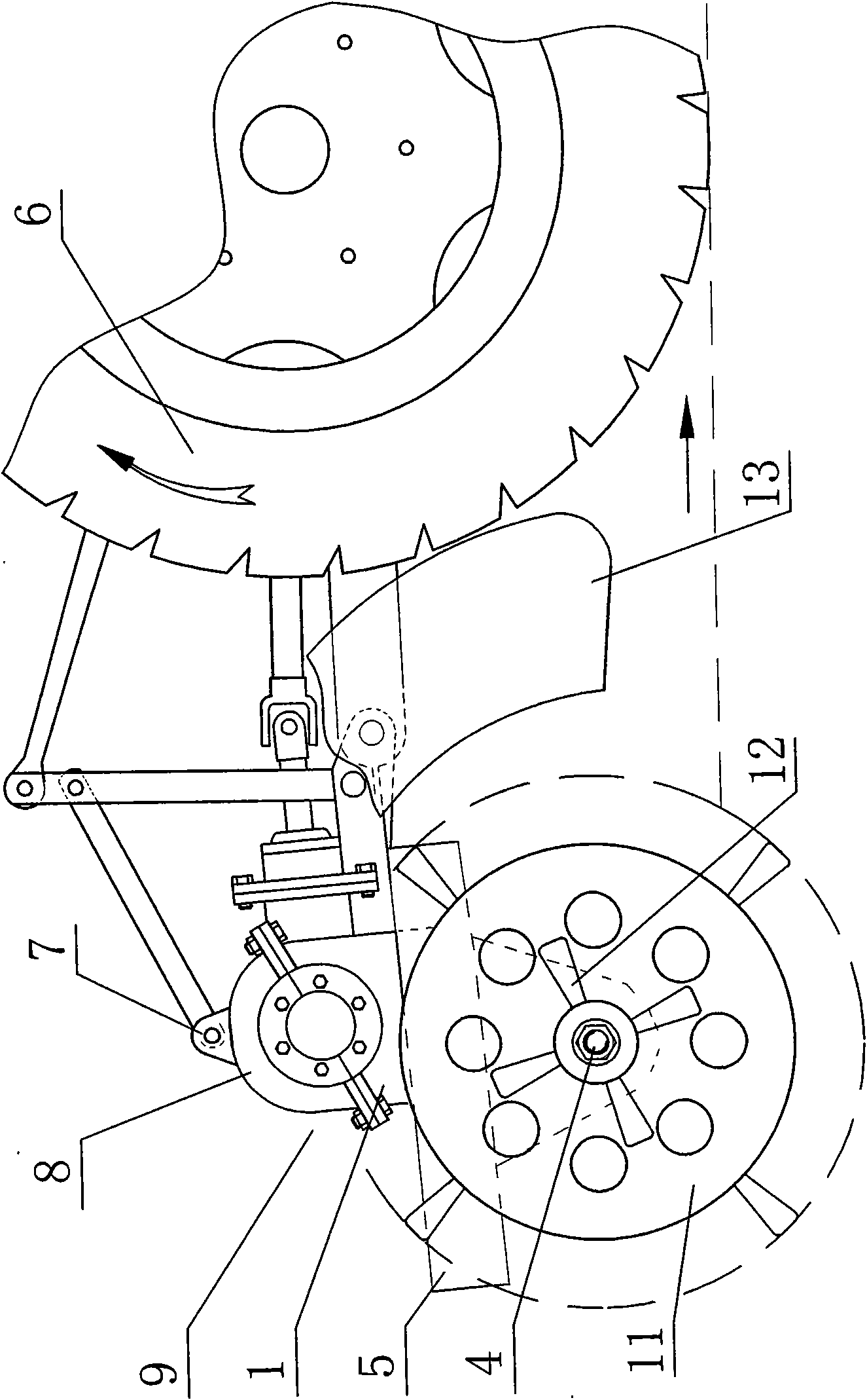
[0044] Figure 3 is with figure 2 Corresponding to the structural diagram shown from the right side of the tractor, in the figure: 1. The lower housing of the gearbox, 4. The extension shaft, 5. The frame of the rotary tiller, 6. The driving wheel of the tractor, 7. The universal joint , 8, the upper casing of the gearbox, 9, the connecting bolts, 11, the ditching cutter head, 12, the rotary tiller. In the fig...

Embodiment 3

[0045] Embodiment 3, a wide-width multifunctional rotary tiller. Figure 4 It is a schematic diagram of assembling a rotary tiller on an extension shaft and expanding it into a wide-width rotary tiller. Figure 4 It is also the rear view direction diagram of the tractor. In the figure: 1. Gear box lower housing, 2. Coulter shaft, 3. Locking pin, 4. Extension shaft, 5. Rotary cultivator frame, 6. Tractor drive wheel, 7. Universal joint, 8. Gear box upper case, 9. Connecting bolts, 10. Stubble fence, 12. Rotary tiller. The coulter shaft tube 14 is a circular tube-shaped structure, which is provided with several rotary cultivators 12, which are set on the extension shaft 4, and have other structures for transmitting torsion such as keys coupled with the extension shaft 4, and nuts on the outside. 15 Tighten.

[0046] If the function of the rotary tiller is to be restored, parts such as the ditching cutter head on the extension shaft and the shaft can be removed, and a dust cove...


PUM


Abstract

The invention relates to a multifunction rotavator, a speed change gear box thereof capable of reversing easily and an extending shaft thereof; the coulter shaft of the rotavator is connected with the power plant of a tractor by the speed change gear box and a rotary blade is arranged at the coulter shaft, characterized in that the speed change gear box of the rotavator is divided into two parts, namely an upper shell body and a lower shell body andassembly opening and closing seam of the upper shell body and the lower shell body is arranged in the central line of the bearing hole of the crown gear shaft, which is positioned above the gear box; the upper shell body and the lower shell body are connected firmly with bolts. In the method of optimization, a connecting mechanism to connect the extending shaft is arranged on at least one end of the coulter shaft. The extending shaft is a ditcher cutter shaft, a cutter shaft of stubble-bury machine or a coulter shaft of the rotavator. The invention is based on the original rotavator and guarantees the functions of the original rotavator and can obtain the functions of burying stubble, furrowing and the like only by easily adjusting and increasing a few part fittings. The gear box features easy dismantle and maintenance, thus being applicable for adjusting the assemble method and maintaining of the gears, reducing the purchase cost for farmers by big margins, facilitating installation and saving the agricultural laboring time.

Description

technical field [0001] The invention belongs to the field of agricultural machinery, and specifically relates to a multifunctional rotary cultivator that can be expanded to be used for stubble burying and ditching, and a variable speed gearbox on the multifunctional rotary cultivator that can be easily reversed, and this Extended shaft on multifunction rotary tiller. Background technique [0002] The existing farmland rotary tiller mounted on the rear of the tractor is a model widely used in agricultural machinery with a long history. Its structure and working principle are: the power of the tractor is transmitted through a pair of bevel gears and several cylindrical gears, Drive the coulter shaft so that the lower edge of the rotary cultivator on the coulter shaft turns backwards (forward rotation) to chop and plow the soil. [0003] The main disadvantage of this type of rotary tiller is that it has a single function and can only be used in farmland with relatively little ...

Claims


Application Information

Patent Timeline
Patent Type & Authority Applications(China)
IPC IPC(8): A01B33/16A01B33/14A01B33/08A01B33/10
Inventor 葛伟岸葛玉明
Owner 葛玉明
Why Eureka
Try Eureka