High-efficiency energy-saving and emission-reduction dust remover

A high-efficiency, energy-saving, dust collector technology, applied in chemical instruments and methods, dispersed particle separation, combined devices, etc., can solve the problems of high one-time investment cost, complex supporting facilities, and high maintenance costs, and achieve low one-time investment cost. The effect of low maintenance cost and low energy consumption

Inactive Publication Date: 2009-10-21
徐景刚
View PDF0 Cites 2 Cited by
  • Summary
  • Abstract
  • Description
  • Claims
  • Application Information

AI Technical Summary

Problems solved by technology

[0002] At present, the dust collectors commonly used in domestic industrial dust removal include sedimentation dust collectors, inertial dust collectors, cyclone dust collectors, filter dust collectors, electric dust collectors, and wet dust collectors. These dust collectors are common: low dust removal efficiency, high energy consumption, maintenance Problems such as high cost, complex supporting facilities, and high one-time input cost

Method used


Image

  • High-efficiency energy-saving and emission-reduction dust remover
  • High-efficiency energy-saving and emission-reduction dust remover
  • High-efficiency energy-saving and emission-reduction dust remover

Examples


Embodiment 1

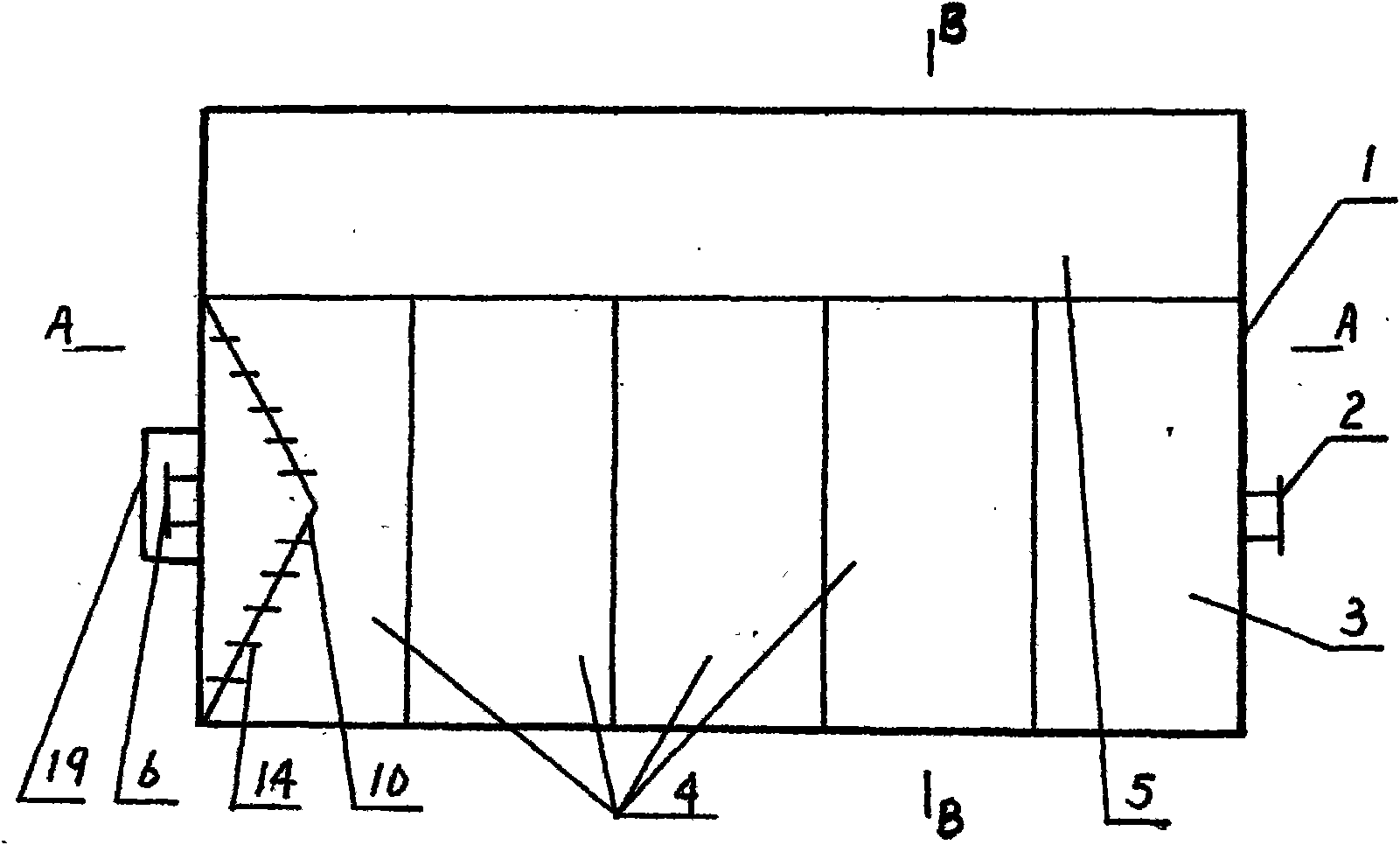
[0019] See figure 1 , figure 2 and image 3 , is a high-efficiency, energy-saving and dust-reducing dust collector with a reinforced concrete structure, consisting of: dust collector shell 1, flue gas inlet 2, fog-making bin 3, dust-reducing bin 4, decontamination pool 5, purified gas outlet 6, fog-making arc plate 7 , automatic adjustment baffle 8, fixed baffle 9, gas purification partition 10, induced draft fan 11, flue gas pipe 13 and purified gas discharger 19, in the dust collector shell 1 is provided with a mist making chamber 3 and a dust suppression chamber 4 and the decontamination tank 5, the bottoms of the mist-making chamber 3 and the dust-removing chamber 4 are slope-shaped and connected with the decontamination pond 5, and the fog-making chamber 3 and the dust-removing chamber 4 are isolated from the atmosphere by a water seal.

[0020] The dust collector shell 1 is made of reinforced concrete with a rectangular parallelepiped structure, on one side of which i...

Embodiment 2

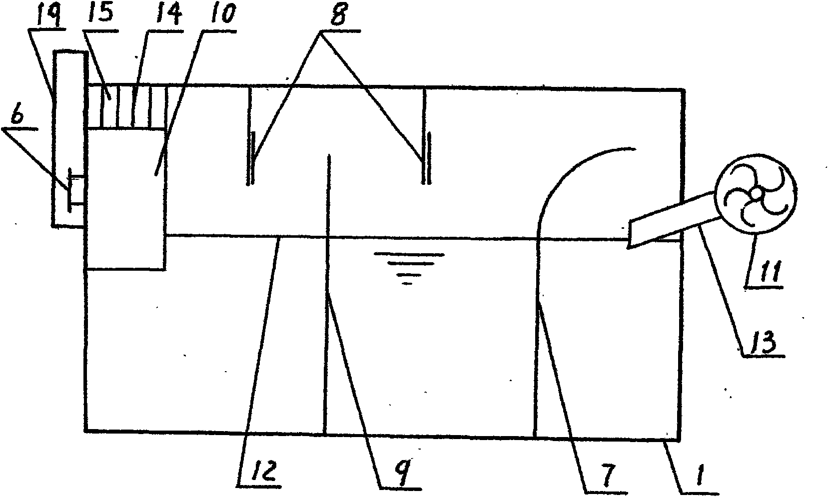
[0027] See Figure 4 and Figure 5 , is a high-efficiency energy-saving and dust-reducing steel structure, consisting of: dust collector shell 1, flue gas inlet 2, fog making chamber 3, dust reduction chamber 4, water tank 16, purified gas outlet 6, fog making arc plate 7, automatic It consists of adjusting baffle 8, fixed baffle 9, gas purification partition 10, induced draft fan 11, flue gas pipe 13 and purified gas discharger 19. Inside the dust collector housing 1, there are fog making chamber 3 and dust reduction chamber 4. A water adding tank 16 is provided outside the dust collector housing 1 through which water is replenished.

[0028] The dust collector shell 1 is made of steel structural parts into a rectangular parallelepiped structure, and a conical sludge bin 17 and a sewage valve 18 are provided at the bottom. The inlet end of the dust collector shell 1 is provided with a flue gas inlet 2. The outlet end of the outlet is provided with a purified gas outlet 6 an...


PUM


Abstract

The invention relates to a high-efficiency energy-saving and emission-reduction dust remover which is characterized by comprising three structural forms: reinforced concrete structure, steel structure or reinforced concrete structure at the lower part and the steel structure at the upper part; a fog generating bin, dust falling bins and a decontamination pool are arranged in a shell of the dust remover, wherein, the bottoms of the fog generating bin and the dust falling bins form a slope shape and are connected with the decontamination pool; an inlet end of the shell of the dust remover is provided with a flue gas inlet, and an outlet end thereof is provided with a purified gas outlet and a purified gas discharge device; a draught fan is connected with the fog generating bin by the flue gas inlet through a flue gas pipeline, and is provided with 2-8 dust falling bins to form multilevel dust falling. The invention can be applied for dust removal and desulfurization of a heating boiler, a steam boiler and a coal-fired power plant, and is also widely applicable to industrial dust removal in the fields such as chemical engineering, steel, building materials, ceramics, metallurgical mine, etc. The invention has the characteristics of high dust removing efficiency, low energy consumption, maintenance cost and one-time investment, needing no associated facility and a high chimney, etc.

Description

technical field [0001] The invention is an industrial dedusting device that can be applied to heating boilers, steam boilers and coal-fired power plants, and can also be widely used in the fields of chemical industry, steel, building materials, ceramics, metallurgy, etc. . Background technique [0002] At present, the dust collectors commonly used in domestic industrial dust removal include sedimentation dust collectors, inertial dust collectors, cyclone dust collectors, filter dust collectors, electric dust collectors, and wet dust collectors. These dust collectors are common: low dust removal efficiency, high energy consumption, maintenance High costs, complex supporting facilities, and high one-time input costs. Contents of the invention [0003] The present invention overcomes the above-mentioned defects, and aims to provide a high-efficiency, energy-saving and dust-reducing dust remover to solve the problem of industrial dust removal. [0004] A brief description of...

Claims


Application Information

Patent Timeline
Patent Type & Authority Applications(China)
IPC IPC(8): B01D50/00
Inventor 徐英楠徐景刚
Owner 徐景刚
Why Eureka
Try Eureka