Equipment driven by compressed air
A technology for compressed air and pneumatic equipment, applied in mechanical equipment, engines, wind turbines, etc., can solve the problems of environmental pollution, high price, waste of social resources, etc., and achieve the effect of large insurance factor, strong practicability and reasonable structure
- Summary
- Abstract
- Description
- Claims
- Application Information
AI Technical Summary
Problems solved by technology
Method used
Image
Examples
Embodiment 1
[0037] Example 1: Compressed Air Box
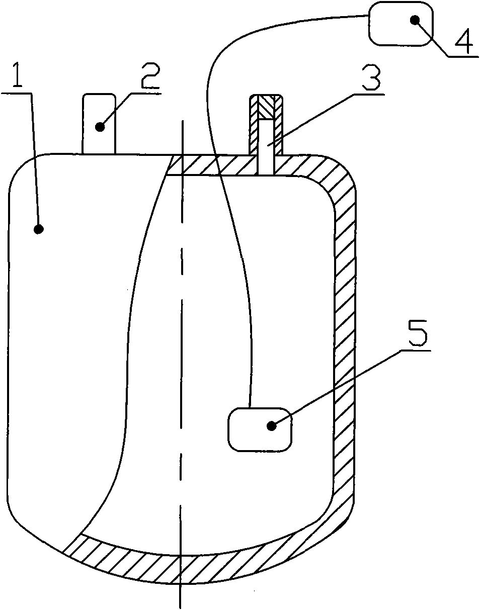
[0038] The structure of the compressed air box is as follows figure 1 As shown: it is composed of a box body 1, a pressure gauge 4 and a pressure probe 5. The top of the box body 1 is provided with an intake valve 2 and an exhaust valve 3 communicating with the inner cavity of the box body. The pressure probe 5 is located in the inner cavity of the box body 1, and the probe is connected with the pressure gauge 4 outside the box body 1 through a metal sensing wire.
[0039] The shape of the compressed air box can be designed according to the needs. The box body 1 is formed by forging, pressing and plastic-casting of the steel plate of the container. According to the design requirements, it can withstand a certain pressure (10kg per cubic centimeter), and can provide a certain amount of power energy in a saturated state. And set a certain safety factor, the intake valve 2 (inflation valve) can ensure that the inflation pressure is 14kg / cm3...
Embodiment 2
[0040] Example 2: Pneumatic equipment
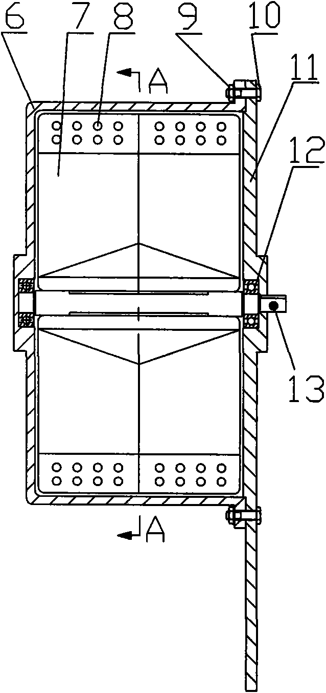
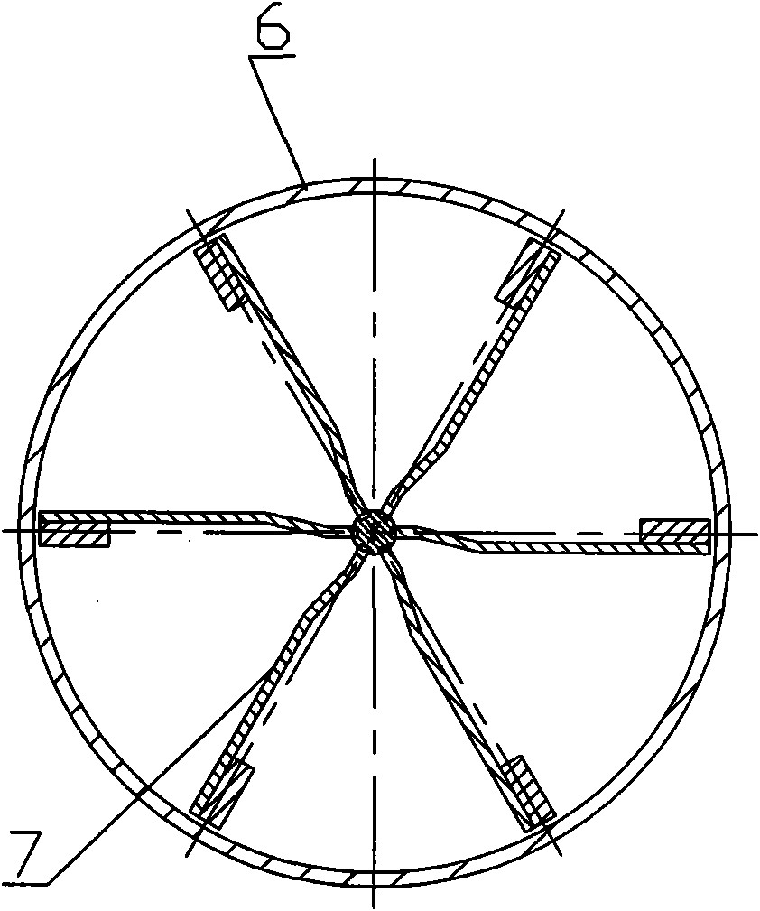
[0041] Taking a wind turbine as an example, its structure is as follows Figure 2 to Figure 14 As shown: the wind turbine is mainly composed of a casing 6 , double cyclone bucket grooved blades 7 and a wind turbine shaft 13 .
[0042] Described casing 6, its edge passes through the screw hole 22 on the wind turbine cover body 11 by bolt 10 and fixes with nut and washer assembly 9 after, makes casing 6 and wind turbine cover body 11 be fixedly connected (see figure 2 ). In order to keep the casing 6 in good contact with the wind turbine cover 11 , they are all provided with closing notches 20 . The casing 6 is provided with a wind turbine exhaust valve 24 and a wind turbine intake valve 25 .
[0043] There are at least 3 pairs of said double cyclone bucket trough blades 7 (hereinafter referred to as blades), the number of which generally depends on the power required by the driven equipment. In order to illustrate the problem, this e...
Embodiment 3
[0047] It can be designed as a compressed air box and pneumatic equipment (wind turbine) ranging from 0.5 horsepower to 200 horsepower. They are used in motor vehicles, landscape vehicles, yachts, vehicles for the disabled, mopeds, and industrial, agricultural, household and other energy-driven equipment.
PUM
 Abstract
Description
Claims
Application Information
 - R&D
- Intellectual Property
- Life Sciences
- Materials
- Tech Scout
- Unparalleled Data Quality
- Higher Quality Content
- 60% Fewer Hallucinations
Browse by: Latest US Patents, China's latest patents, Technical Efficacy Thesaurus, Application Domain, Technology Topic, Popular Technical Reports.
© 2025 PatSnap. All rights reserved.Legal|Privacy policy|Modern Slavery Act Transparency Statement|Sitemap|About US| Contact US: help@patsnap.com


