Method for calibrating three-dimensional micro-touch force sensor

A technology of force sensor and calibration method, applied in the direction of instrument, force/torque/work measuring instrument calibration/test, measurement device, etc. Improve accuracy, reduce calibration error, and reduce the effect of step size

Inactive Publication Date: 2009-10-21
TIANJIN UNIV
View PDF0 Cites 17 Cited by
  • Summary
  • Abstract
  • Description
  • Claims
  • Application Information

AI Technical Summary

Problems solved by technology

In order to accurately calibrate the three-dimensional micro-tactile force sensor, researchers have tried many methods, such as using standard high-precision weights to apply standard force signals to the sensor, while observing the output voltage signal of the sensor, etc., but this method is difficult to operate. It is cumbersome, and the calibration accuracy is greatly affected by the accuracy of the weight and the external environment. The connection method between the sensor and the weight during the calibration process is also a problem that needs to be solved, which affects the calibration accuracy of the sensor.
[0004] In view of the shortcomings of using standard high-precision weights to calibrate the three-dimensional micro-tactile force sensor, the researchers proposed to use the cantilever beam bending deformation method to provide standard micro-force signals, and combined with microscopic vision technology to measure the displacement of the free end of the cantilever beam. The method calibrates the input-output characteristics of the sensor, but the magnification of the microscope in the microscopic vision technology limits the calibration accuracy of the sensor

Method used


Image

  • Method for calibrating three-dimensional micro-touch force sensor
  • Method for calibrating three-dimensional micro-touch force sensor
  • Method for calibrating three-dimensional micro-touch force sensor

Examples


Embodiment Construction

[0035] The calibration method of the three-dimensional micro-tactile force sensor of the present invention will be described in detail below in conjunction with the accompanying drawings of the embodiments.

[0036] The calibration method of the three-dimensional micro-tactile force sensor of the present invention comprises the following steps:

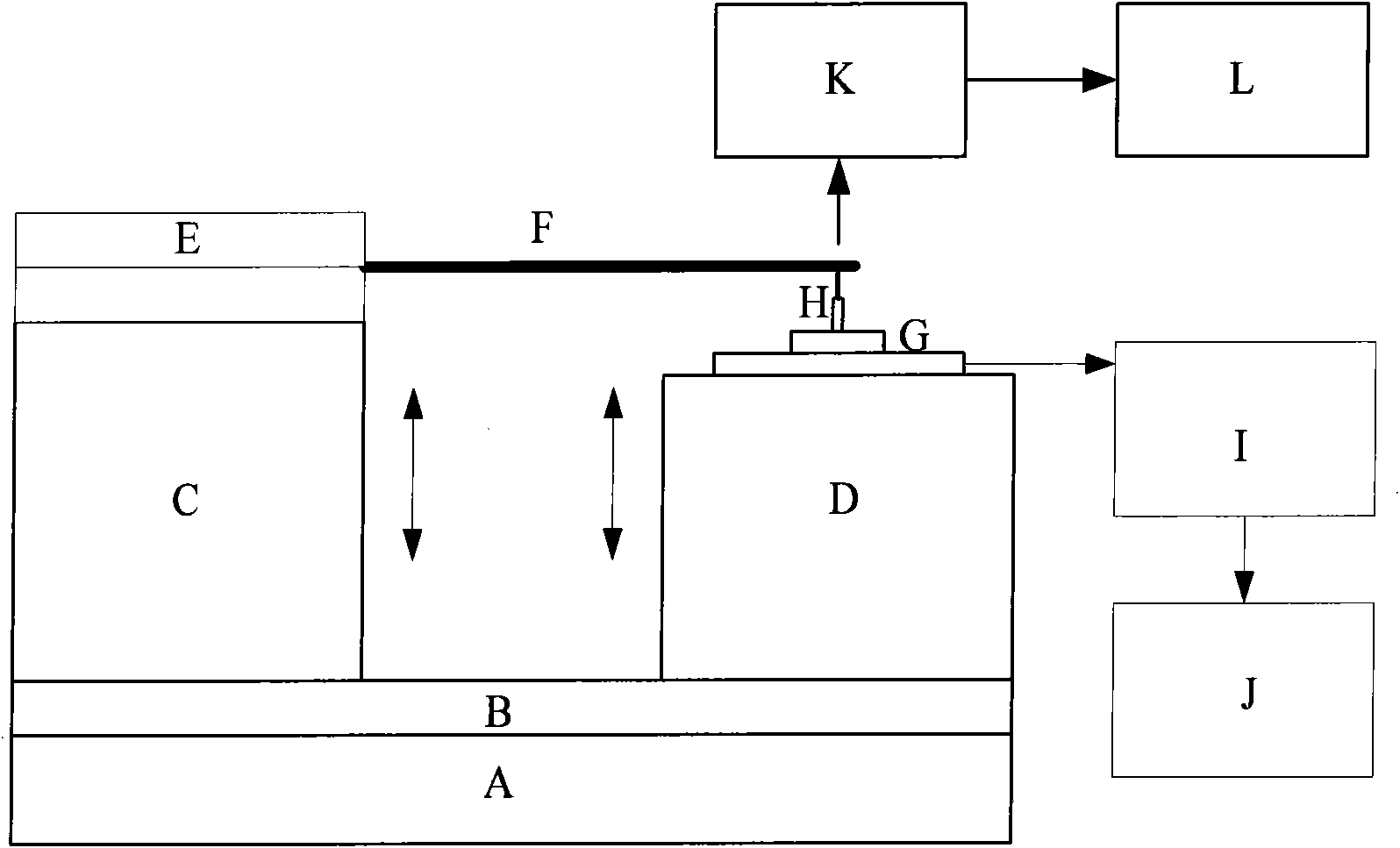
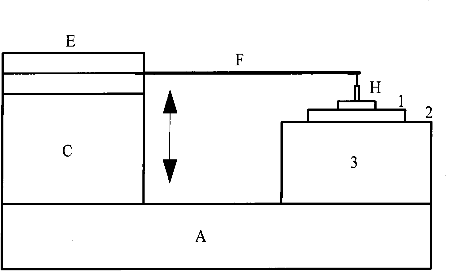
[0037] (1) Using the principle of cantilever beam bending deformation to obtain the small force signal required for the calibration of the three-dimensional micro-tactile force sensor;

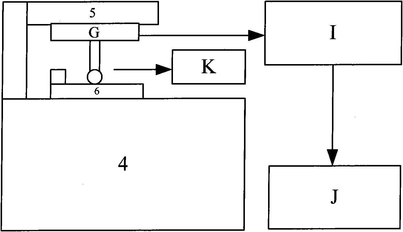
[0038] (2) Measure the elastic coefficient of the cantilever beam;

[0039] The measurement of the elastic coefficient of the cantilever beam is realized by making the free end of the cantilever beam deflect through the micro-movement platform, and then measuring the magnitude of the force applied to the balance by the free end of the cantilever beam. Specifically, build as figure 2 In the cantilever beam elastic coefficient calibration system show...


PUM


Abstract

The invention relates to a method for calibrating a three-dimensional micro-touch force sensor, which comprises the following steps: adopting the bending deformation principle of a cantilever beam to acquire a micro-force signal required by calibrating the three-dimensional micro-touch force sensor; measuring the elastic coefficient of the cantilever beam; based on the cantilever beam of the known elastic coefficient, establishing a calibrating system of the three-dimensional micro-touch force sensor, and measuring input-output property coefficients of the calibrating system by applying acting force of different intensity to the sensor; measuring the measuring bar displacement property of the three-dimensional micro-touch force sensor; according to the measured elastic coefficient of the cantilever beam, the input-output property coefficients of the calibrating system and the measuring bar displacement property coefficient of the sensor, establishing a mathematical model to acquire the input-output property coefficients of the sensor; and according to a zero output voltage value of the sensor and the input-output property coefficients of the sensor, establishing an input-output property equation of the sensor so as to finish the calibration of the three-dimensional micro-touch force sensor. The method can realize the calibration of the output property of the three-dimensional micro-touch force sensor, and has the advantages of high and reliable precision and good repeatability.

Description

technical field [0001] The invention relates to a calibration method of a sensor. In particular, it relates to a calibration method of a three-dimensional micro-tactile force sensor which compensates the error caused by the displacement of the sensor rod during the calibration process based on the displacement characteristics of the sensor rod. Background technique [0002] With the rapid development of micro-nano technology and biotechnology and the rapid development of emerging disciplines such as micro-manipulation / micro-processing, micro-force measurement in micro-scale environments has attracted widespread attention. Biomechanical research in the field of biomedicine, single-cell manipulation; micromachining / micromanipulation in the field of aerospace, manufacturing of micro-spacecraft; scanning probe microscopy in the field of precision engineering, etc., all have the potential to achieve micro-force measurement in the micro-scale space. problem. At present, the micr...

Claims


Application Information

Patent Timeline
Patent Type & Authority Applications(China)
IPC IPC(8): G01L25/00
Inventor 栗大超王和牛傅星徐可欣胡小唐
Owner TIANJIN UNIV
Why Eureka
Try Eureka