
Liquid crystal display panel and liquid crystal display device

A technology of liquid crystal display panels and liquid crystal display devices, applied in static indicators, nonlinear optics, optics, etc., can solve the problems of reduced brightness of three-dimensional stereoscopic images, and achieve the effects of reducing intensity, increasing luminance, and reducing power consumption

Inactive Publication Date: 2009-10-21
CPT DISPLAY TECH SHENZHEN +1
View PDF0 Cites 19 Cited by
  • Summary
  • Abstract
  • Description
  • Claims
  • Application Information

AI Technical Summary

Problems solved by technology

[0007] The purpose of the embodiments of the present invention is to provide a liquid crystal display panel, aiming to solve the problem of a large decrease in the brightness of the three-dimensional images displayed by the liquid crystal display panel with the existing design of switching the liquid crystal layer

Method used


Image

  • Liquid crystal display panel and liquid crystal display device
  • Liquid crystal display panel and liquid crystal display device
  • Liquid crystal display panel and liquid crystal display device

Examples


Embodiment Construction

[0018] In order to make the object, technical solution and advantages of the present invention clearer, the present invention will be further described in detail below in conjunction with the accompanying drawings and embodiments. It should be understood that the specific embodiments described here are only used to explain the present invention, not to limit the present invention.

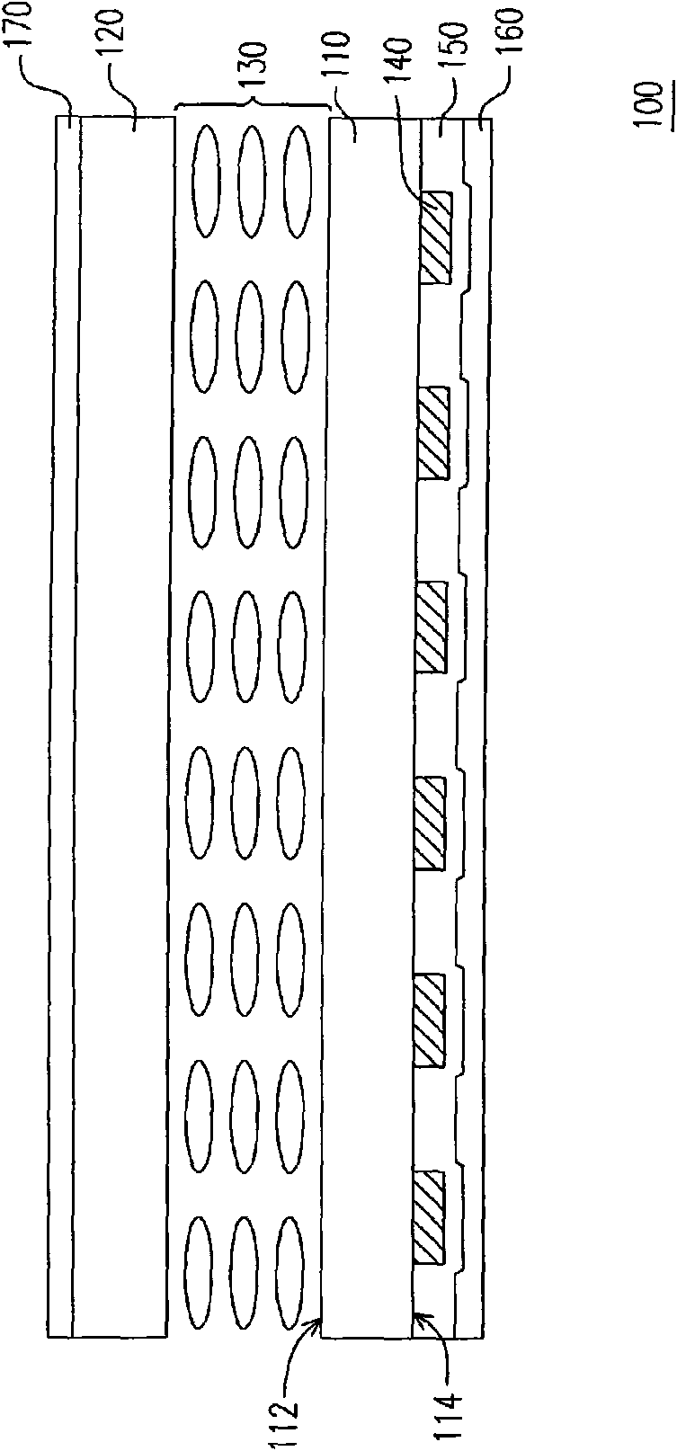
[0019] figure 1 is a schematic diagram of a liquid crystal display panel provided by an embodiment of the present invention. Please refer to figure 1 , in the embodiment of the present invention, the liquid crystal display panel 100 includes an active device array substrate 110 , a color filter substrate 120 , a liquid crystal layer 130 and a grating 140 . The active device array substrate 110 is, for example, a thin film transistor (ThinFilm Transistor, TFT) array substrate, which has an upper surface 112 and a lower surface 114 . Generally speaking, the thin film transistor array substrate mai...


PUM


Abstract

The invention is applicable to the technical field of liquid crystal display and provides a liquid crystal display panel and a liquid crystal display device, wherein the liquid crystal display panel comprises an active component array substrate with an upper surface and a lower surface, a colorful filtering substrate arranged in the opposite direction of the active component array substrate, a liquid crystal layer arranged between the upper surface of the active component array substrate and the colorful filtering substrate, and a grating arranged on the lower surface of the active component array substrate. In the embodiment of the invention, the lower surface of the active component array substrate is provided with the grating, therefore, when a backlight module emits a light beam, the light beam can achieve the grating by an optical film; furthermore, the grating can lead the light source blocked by the lightproof / light-absorbing grating in the prior art to become an available light source by passing the clearance of the gratings again after multiple reflection of the grating with the reflective characteristic, thus improving the brilliance when the liquid crystal display panel displays stereoscopic images and reducing the intensity of the backlight module simultaneously.

Description

technical field [0001] The invention belongs to the technical field of liquid crystal display, and in particular relates to a liquid crystal display panel and a liquid crystal display device. Background technique [0002] Parallax Stereogram refers to enabling human eyes to see stereoscopic images. This method is to cut the individual images for the left eye and the right eye according to the vertical pixel line, and then rearrange and fuse them into a new image according to the odd and even, and add a parallax barrier grating (Parallax) in front of the fused image when viewing. Barrier), so that the left and right eyes can only see the left image and the right image in the fused graphics by using the shielding effect of parallel gratings, so as to form a three-dimensional image in the brain, which is the parallax barrier method. [0003] Since the parallax barrier method utilizes occlusion so that the left eye and the right eye can only see the left image and the right ima...

Claims


Application Information

Patent Timeline
IPC IPC(8): G02F1/133G02F1/1362
Inventor 陈逸明林振吉黄彦馀陈建宇
Owner CPT DISPLAY TECH SHENZHEN
Features
  • Generate Ideas
  • Intellectual Property
  • Life Sciences
  • Materials
  • Tech Scout
  • Unparalleled Data Quality
  • Higher Quality Content
  • 60% Fewer Hallucinations
Learn More