Method for controlling microwave vehicle detecting radar

A technology of vehicle detection and control method, which is applied in the direction of road vehicle traffic control system, traffic flow detection, traffic control system, etc., can solve problems such as false alarms, large blind spots for speed measurement, and errors.

Inactive Publication Date: 2009-10-21
中国人民解放军理工大学气象学院
View PDF0 Cites 43 Cited by
  • Summary
  • Abstract
  • Description
  • Claims
  • Application Information

AI Technical Summary

Problems solved by technology

[0003] Based on the video target recognition technology, the detector is susceptible to the trapezoidal error caused by the camera installation inclination and the road surface inclination when detecting the vehicle position. And there will be a large error, so the application field is limited
[0004] When installing a detector based on ground sensing coil technology, the construction of the embedded coil is complicated, and the road must be closed and the road surface damaged
When the vehicle is speeding and heavily loaded, the damage rate of the coil is high, and even the average life of the coil in some road sections is only a few months. At the same time, the detector based on the ground induction coil technology is also prone to false alarms when it is disturbed by rain
[0005] Detectors based on infrared or laser technology are relatively accurate in measurement, but they also have the following disadvantages: limited by the principle of laser speed measurement, the laser beam must be aimed at the plane reflection point perpendicular to the laser beam, and because the measured vehicle is too far away and in the In the moving state, or the plane of the vehicle body is not large, the success rate of

Method used


Image

  • Method for controlling microwave vehicle detecting radar
  • Method for controlling microwave vehicle detecting radar
  • Method for controlling microwave vehicle detecting radar

Examples


Embodiment Construction

[0071] The present invention will be further described below in conjunction with the accompanying drawings.

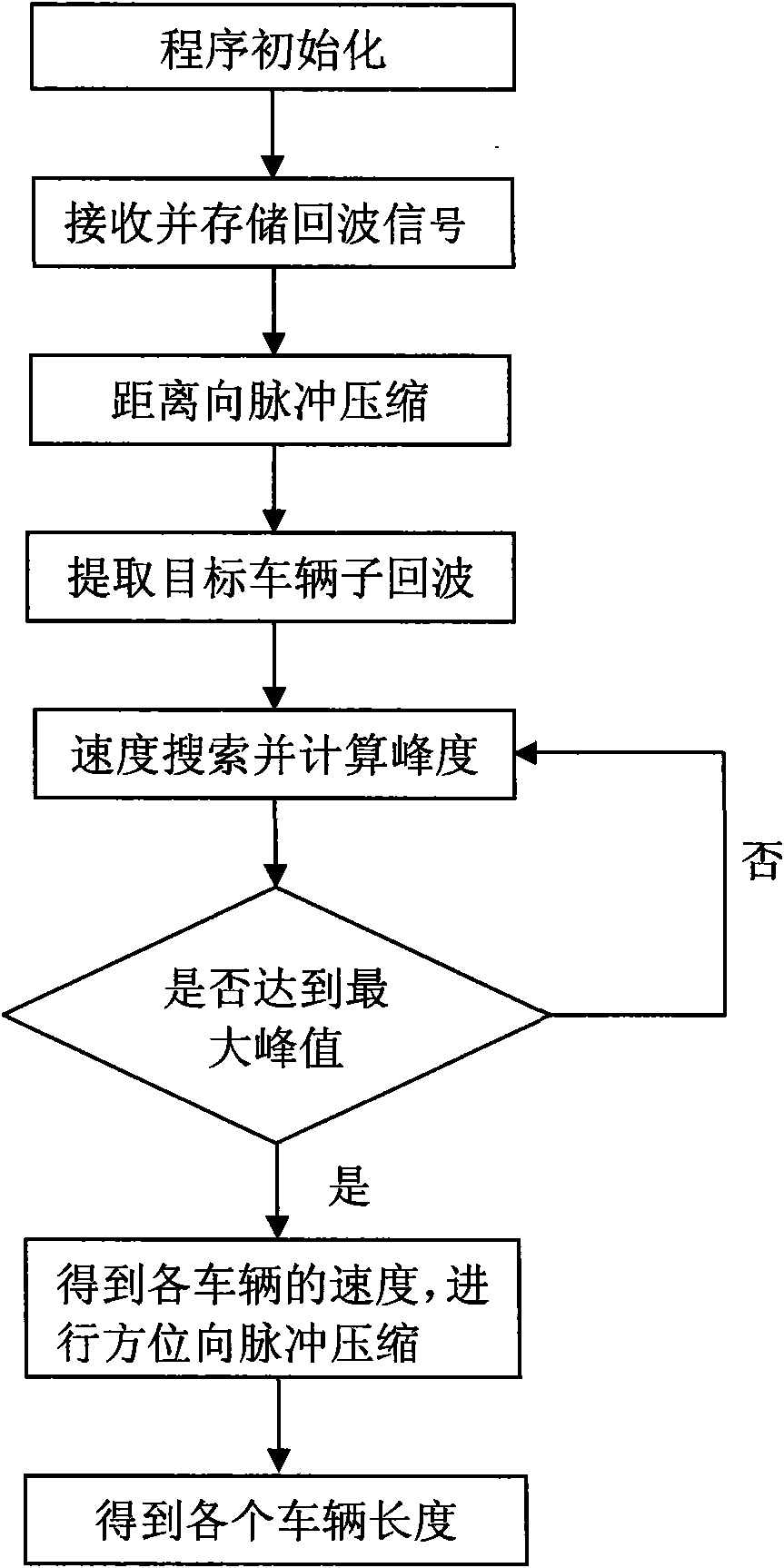
[0072] Such as figure 1 Shown, the present invention comprises the steps:

[0073] Step 1. Program initialization, which is to assign values ​​to relevant working parameters of the detection radar;

[0074] Step 2, range-wise pulse compression, that is, perform pulse compression processing on the collected target echo signals to obtain whether there are vehicles in each lane;

[0075] Step 3, extract the target sub-echo data of each vehicle from the entire echo signal after distance compression, determine whether each target is moving or stopped, and provide a basis for subsequent processing steps;

[0076] The further description of step three is as follows: the sub-echoes of each target vehicle are extracted respectively, so as to process and analyze each sub-echo data respectively. The sub-echo data include the sub-echo data of the moving vehicle and the sub-echo da...


PUM


Abstract

The invention discloses a method for controlling microwave vehicle detecting radar, comprising the following steps: microwave detecting radar work parameter is evaluated; pulse compression in the range direction is carried out; sub-echo of each target vehicle is respectively extracted, and whether advancing vehicle exists is judged, speed search is carried out on data of each sub-echo of advancing vehicle, one matched filtering function is obtained after each search, pulse compression in the azimuth direction is carried out, and then the kurtosis value is calculated; if the largest kurtosis value is obtained, the search speed corresponding to the largest kurtosis value is the traveling speed of the vehicle, frequency modulation slope in the azimuth direction is calculated according to the speed and pulse compression in the azimuth direction is carried out, and then signals of each range gates are added and are compared with the set threshold to obtain vehicle length; if the largest kurtosis value is not obtained, then search is kept on by returning to the previous step. The invention has numerous monitoring lanes, wide detection range and more precise detecting speed, can detect vehicle with low speed or even standing vehicle precisely, and can estimate vehicle length, thereby facilitating traffic control.

Description

technical field [0001] The invention relates to a control method of a microwave vehicle detection radar, which is mainly used to detect the speed, quantity and vehicle length information of vehicles traveling in multiple lanes. Background technique [0002] In the field of road traffic monitoring, the detection of vehicle speed usually includes practical products such as detectors based on video target recognition technology, detectors based on ground sensing coil technology, detectors based on infrared or laser technology, and detection radars based on microwave technology. Due to the different technologies used, the corresponding equipment has its own characteristics and certain deficiencies. [0003] Based on the video target recognition technology, the detector is susceptible to the trapezoidal error caused by the camera installation inclination and the road surface inclination when detecting the vehicle position. However, there will be a large error, so the application...

Claims


Application Information

Patent Timeline
IPC IPC(8): G08G1/01G08G1/052G01S13/91
Inventor 关振红李勇陈加清周树道赵军顾怀中沈超玲
Owner 中国人民解放军理工大学气象学院
Why Eureka
Try Eureka