Converting type symmetrical power amplifier

A power amplifier and symmetrical technology, applied in the field of audio power amplifier circuit and audio power amplifier, can solve the problems of less adoption, greater influence of electromagnetic radiation circuit, and complicated auxiliary switch circuit.

Inactive Publication Date: 2009-10-21
施少俊
View PDF1 Cites 2 Cited by
  • Summary
  • Abstract
  • Description
  • Claims
  • Application Information

AI Technical Summary

Problems solved by technology

If you want to use a single power supply to start the audio power amplifier, you must use two sets of identical circuits to output mutually inverse signals at the final stage of the power amplifier and form a bridge structure to drive the load. The disadvantage of this is: the use of components The quantity is large, which is equivalent to using two sets of power amplifier components to synthesize a power amplifier with only one channel, and because the electromagnetic radiation generated by the large current and high voltage of the final stage of the power amplifier has a greater impact on the circuit, and because the respective gain of the two sets of circuits There will always be errors and the loop negative feedback control is difficult, so the output signal of the final stage of the power amplifier is not good at the load, which is the main reason why this type of audio power amplifier is rarely used
[0004] Another audio power amplifier powered by a single power supply adopts the transformer coupling method, which is rarely used because of its relatively old technology and relatively poor sound quality.
[0005] Another kind of audio power amplifier powered by a single power supply is a power amplifier in the form of a switch. Because of its complicated switching circuit, it is rarely used in practical applications.

Method used


Image

  • Converting type symmetrical power amplifier

Examples


Embodiment Construction

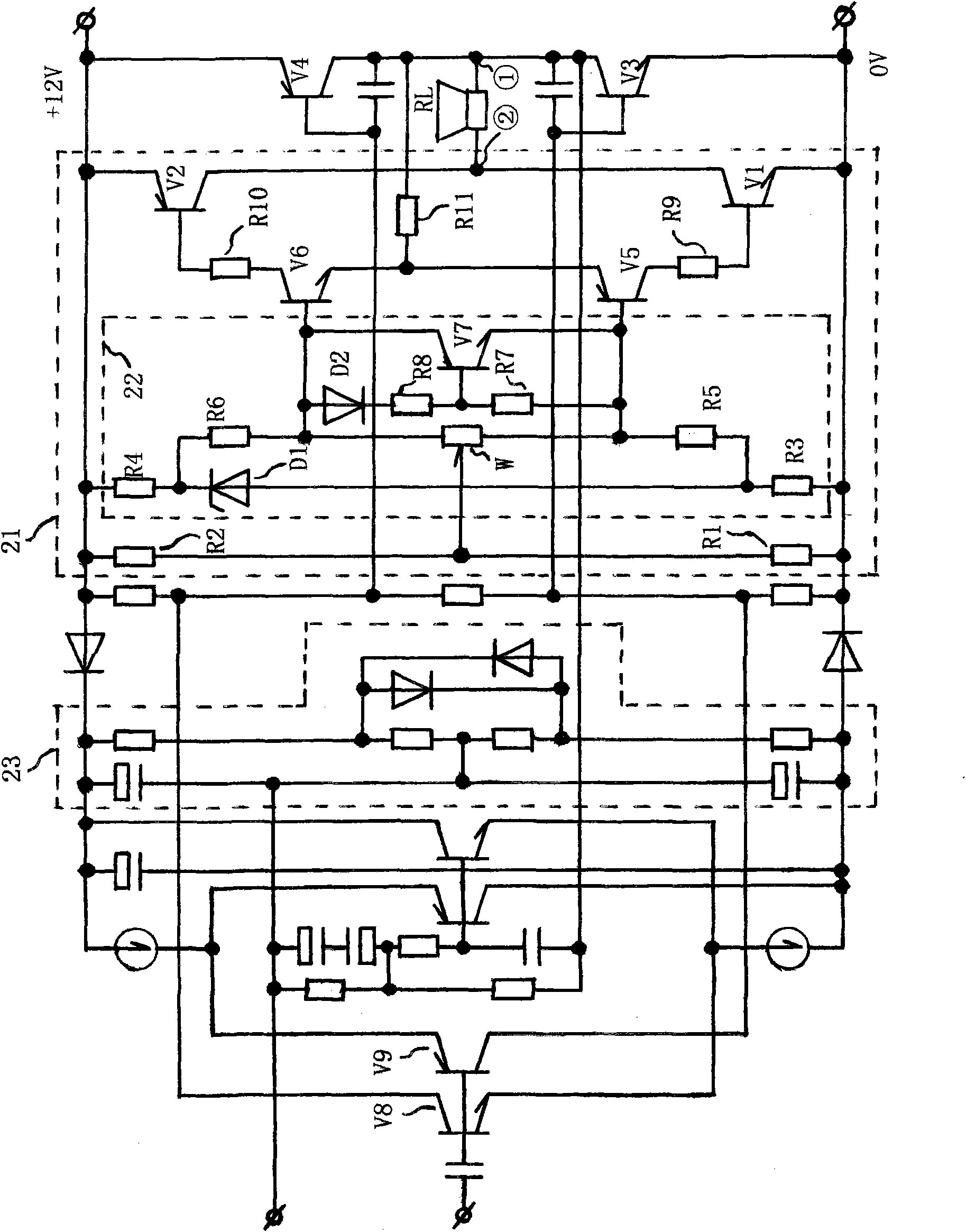
[0019] It can be seen from the drawings in the manual that the composition of the entire power amplifier circuit is very ordinary, but the idea is ingenious. Whole power amplifier has mainly added the circuit in 21 among the accompanying drawings except the connection method roughly the same as usual audio power amplifier, uses this circuit and can allow power amplifier to run with single-way power supply.

[0020] The circuit in 22 in the accompanying drawing is to provide the bases of the first complementary transistors V5 and V6 with a static bias current after secondary voltage regulation, wherein the second resistor is composed of two resistors R3, R4 and one voltage regulator transistor D1 The first-stage voltage-stabilizing bias, and the second-stage voltage-stabilizing bias composed of 1 diode D2, 4 resistors R5, R6, R7, R8 and 1 triode V7.

[0021] The realization of the circuit is: press figure 1 The schematic diagram of the commutating symmetrical power amplifier c...


PUM


Abstract

The invention belongs to the audio power amplifying circuit and relates to a converting type symmetrical power amplifier, comprising a starting resistor R11, first complementary tubes V5 and V6, second complementary tubes V1 and V2, high-precision equivalent resistors R1 and R2 and a two-stage pressure-stabilizing bias circuit; the invention is characterized in that the converting type symmetrical power amplifier provides a two-stage pressure-stabilizing bias method to lead the base bias current and electric potential of the first complementary tubes V5 and V6 to be stably fixed when in static state; the high-precision equivalent resistors R1 and R2 are used for obtaining the center of the power supply voltage in a partial voltage and have the function of leading the sound quality to be more clear in the circuit; one end of the starting resistor R11 is connected with the common emitter of the first complementary tubes V5 and V6 and the other end thereof is connected with (1) end of a load RL; and the first complementary tubes V5 and V6 and the second complementary tubes V1 and V2 form symmetrical two-stage direct coupling amplifying circuit. The circuit formed by adopting the method can use a single-way power supply to operate acoustics and power amplifiers and is applicable to acoustics and power amplifiers below 10W.

Description

[0001] The guide-reversing symmetrical power amplifier is the entire content of my previous patent application number CN200720074437.5, which is written repeatedly and loaded into this patent application. Technical field: [0002] The technical field of the present invention is: audio frequency power amplifying circuit, which relates to a conductor-changing symmetrical power amplifier. This power amplifier is an audio power amplifier with a new concept of using a single power supply that has never appeared in any audio circuit at home and abroad. The invention is suitable for audio power amplifiers below 10W, especially for small power amplifiers of earphones. Background technique: [0003] In the prior art, two-way symmetrical power supply is generally used to start the audio power amplifier. If you want to use a single power supply to start the audio power amplifier, you must use two sets of identical circuits to output mutually inverse signals at the final stage of the p...

Claims


Application Information

Patent Timeline
Patent Type & Authority Applications(China)
IPC IPC(8): H03F3/20
Inventor 施少俊
Owner 施少俊
Why Eureka
Try Eureka