Serial-parallel type multi-evaporator loop heat pipe

A technology of loop heat pipes and evaporators, which is applied to circuits, electric solid-state devices, semiconductor devices, etc., can solve the problems of large heat dissipation devices, high cost, and high noise, and achieves easy positioning and installation, improved heat conduction efficiency, and reduced total cost Effect

Inactive Publication Date: 2009-10-28
BEIJING AVC TECH RES CENT
View PDF0 Cites 24 Cited by
  • Summary
  • Abstract
  • Description
  • Claims
  • Application Information

AI Technical Summary

Problems solved by technology

They can solve the heat dissipation problem of high-power devices to a certain extent, but there are the following disadvantages: (1) fan + heat sink, in order to enhance the heat dissipation capacity of the heat dissipation device, only by increasing the area of ​​the heat dissipation fins and increasing the fan speed, resulting in The result is that the noise is large, the heat sink is large and heavy, which is not conducive to installation and will generate a lot of pressure on electronic devices; (2) fan + heat pipe + radiator can solve the shortcomings in method 1, but it will increase the mechanism itself. The complexity, design and installation of heat pipes are often limited by the actual structure, and under the action of limited heat pipes, its heat dissipation capacity is still limited; 3) Liquid cooling technology, which surpasses the above two methods in performance, and liquid cooling heat dissipation technology The potential is very high. If a small liquid cooling device is optimized in performance, it can dissipate 1000 watts of heat under the premise of controlling noise (the overall thermal resistance of the liquid cooling radiator can be as low as 0.12°C / W or less. )
Due to the limitations of the loop heat pipe itself, the potential of a single loop heat pipe cannot be fully explored, especially for loop heat pipes with high manufacturing costs. For the heat dissipation of multi-point high-calorie heat sources, if a single evaporator structure is used, the overall cost is expensive. and cannot coordinate the balance of cooling requirements between heat sources

Method used


Image

  • Serial-parallel type multi-evaporator loop heat pipe
  • Serial-parallel type multi-evaporator loop heat pipe
  • Serial-parallel type multi-evaporator loop heat pipe

Examples


Embodiment Construction

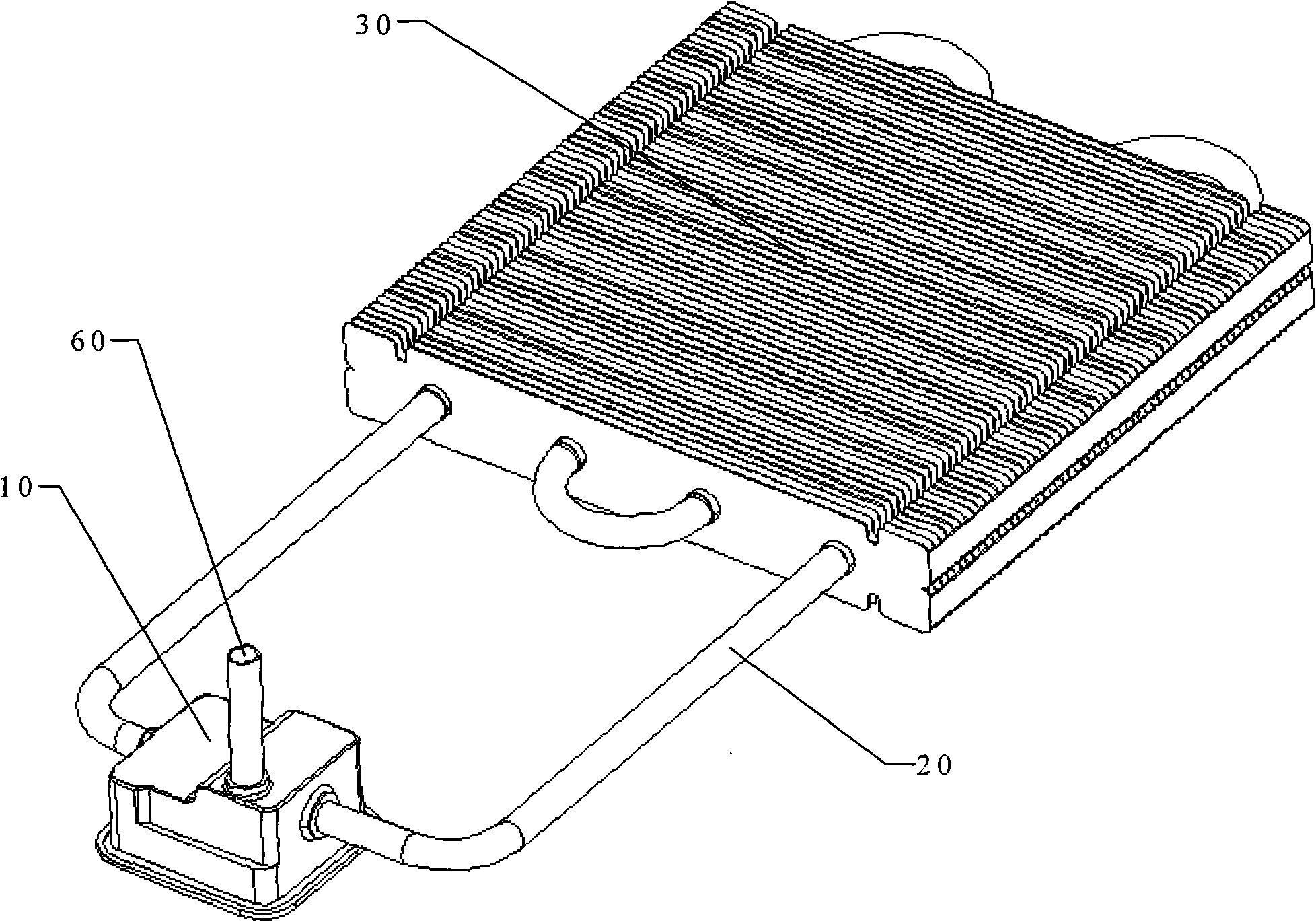
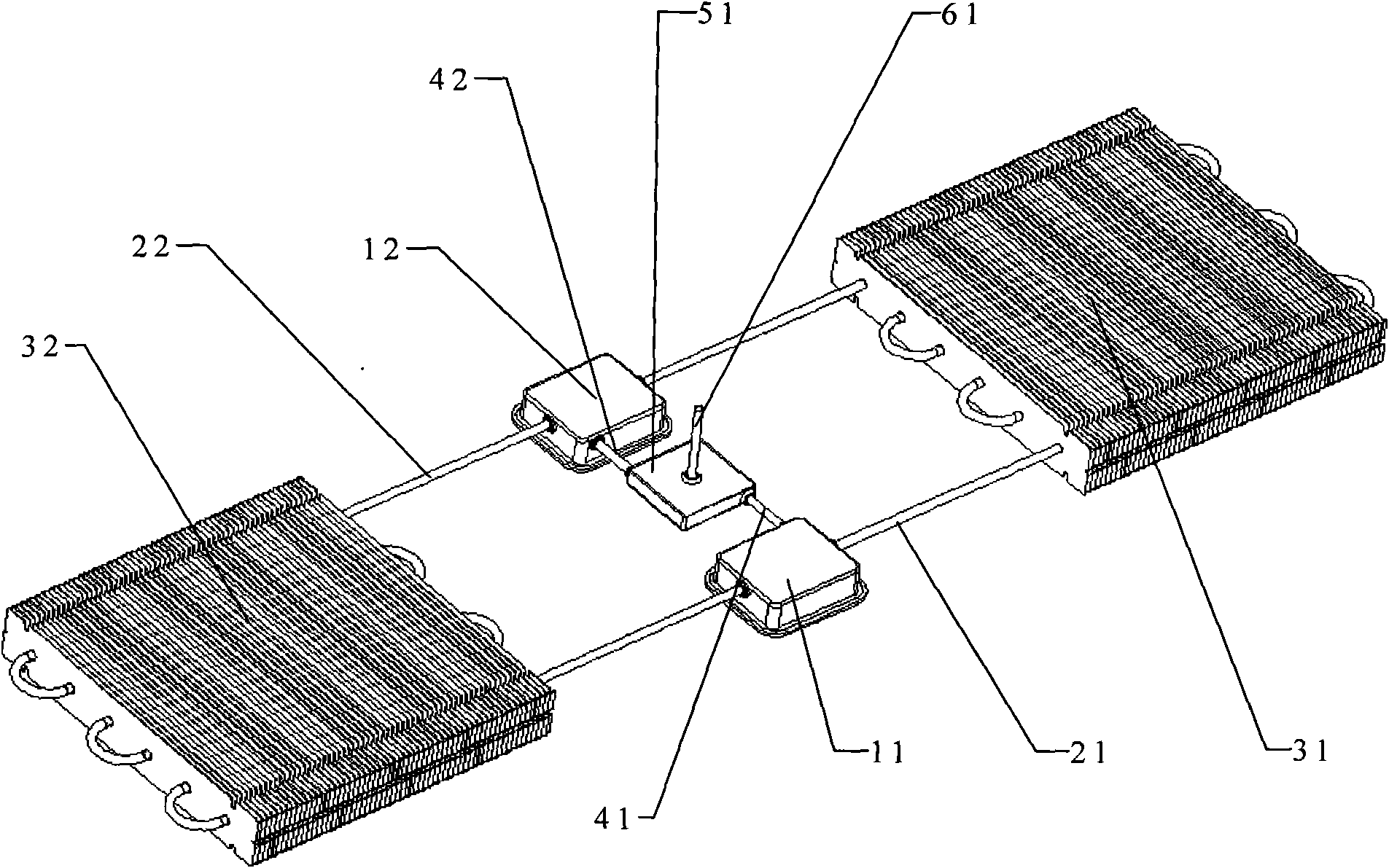
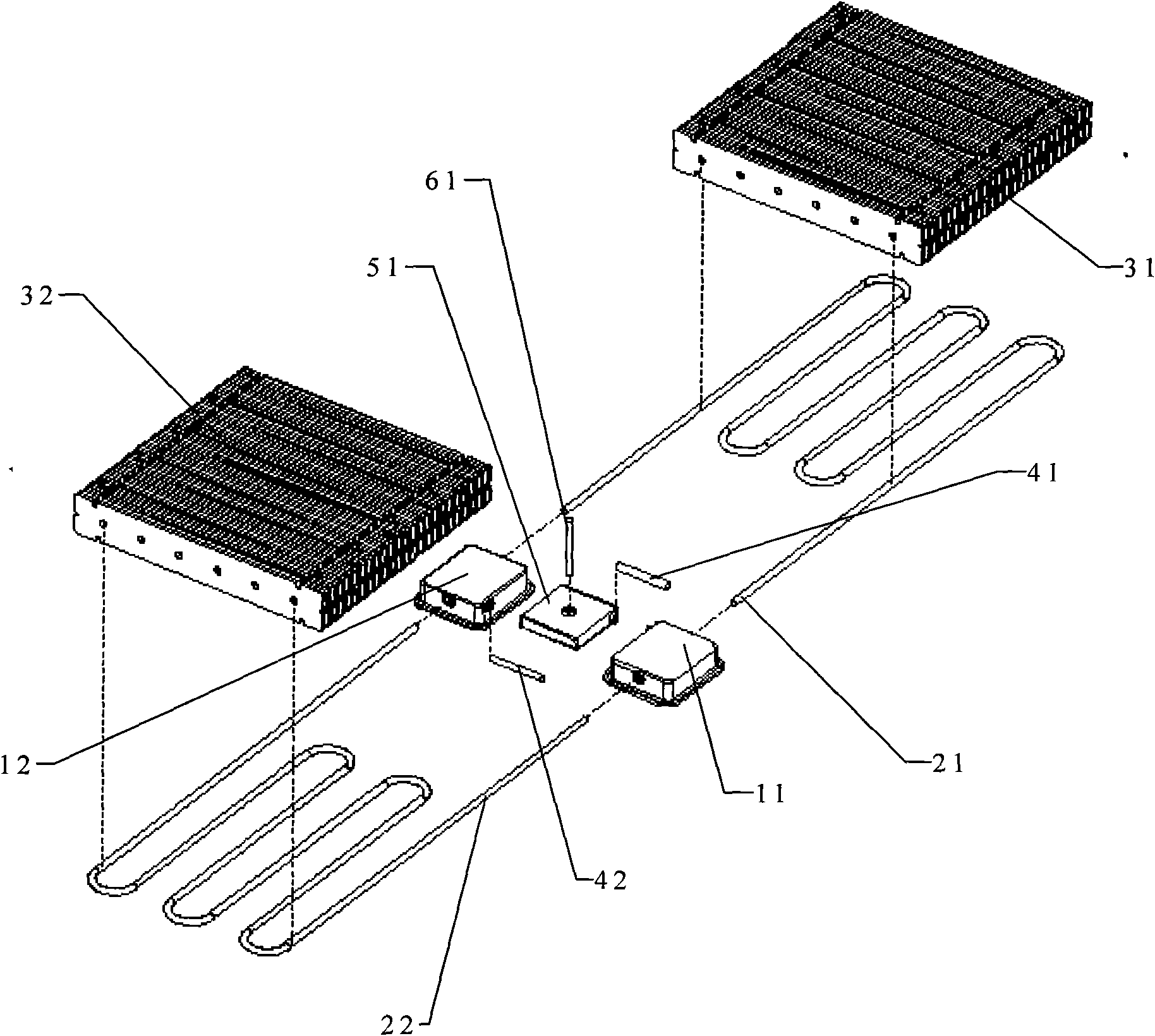
[0033] The invention is a series-parallel multi-evaporator loop heat pipe, please refer to the specific structure figure 2 , image 3 An embodiment shown, the embodiment of the series-parallel multi-evaporator loop heat pipe mainly includes two sets of loop heat pipe evaporators 11, 12, two loop heat pipe gas-liquid pipelines 21, 22, two sets of loop heat pipes Heat pipe condensers 31, 32, a group of loop heat pipe working liquid compensation chambers 51, loop heat pipe working liquid compensation pipelines 41, 42, and loop heat pipe liquid filling and vacuumizing pipelines 61.

[0034] The liquid inlets and steam outlets of the two groups of evaporators 11, 12 are connected in series by two gas-liquid pipelines 21, 22, that is, the steam outlet of the evaporator 11 and the liquid inlet of the evaporator 12 are connected through a gas-liquid pipeline 22 ; At the same time, the liquid inlet of the evaporator 11 and the steam outlet of the evaporator 12 are connected through t...


PUM


Abstract

A serial-parallel type multi-evaporator loop heat pipe comprises at least two groups of evaporators, at least two gas-liquid pipelines, at least two groups of condensers and at least one group of working fluid compensation chamber. The arrangement of a plurality of evaporators adopts a sequential serial-parallel type, namely the gas-liquid pipelines are used for connecting a back evaporator liquid inlet with a front steam outlet and connecting the steam outlet of the final evaporator with the first liquid inlet of the first evaporator; the gas-liquid pipeline is provided with the condenser; and the multi-group of the evaporators commonly use at least one group of working fluid compensation chambers that are connected with each other by the liquid compensation pipelines. The loop heat pipe can meet the simultaneous heat dissipation requirement of a plurality of heat sources, is mainly applicable to the heat dissipation of computer chips, and can be also used for the cooling of light-emitting diode lighting equipment, chips in communication industries and internal high-energy heating parts of military, medical and aerospace equipment.

Description

technical field [0001] The invention relates to the field of heat dissipation product manufacturing, in particular to a structure of a series-parallel multi-evaporator loop heat pipe. Background technique [0002] The cooling of high-power heat sources, especially high-power electronic chips, is a very important technical link in electronics, computers, communications and optoelectronic equipment. At present, the commonly used methods for heat dissipation of high-power electronic devices in the market include the following: (1) fan + radiator; (2) fan + heat pipe + radiator; (3) fan + liquid cooling technology. They can solve the heat dissipation problem of high-power devices to a certain extent, but there are the following disadvantages: (1) fan + heat sink, in order to enhance the heat dissipation capacity of the heat dissipation device, only by increasing the area of ​​the heat dissipation fins and increasing the fan speed, resulting in The result is that the noise is la...

Claims


Application Information

Patent Timeline
Patent Type & Authority Applications(China)
IPC IPC(8): F28D15/02H01L23/427H05K7/20
CPCH01L2924/0002
Inventor 李骥王大明
Owner BEIJING AVC TECH RES CENT
Why Eureka
Try Eureka