Coupling inductor applicable to multi-phase interleaved parallel converter

A technology of coupled inductance and multi-phase interleaving, applied in the field of coupled inductance, can solve problems such as restricting volume, achieve the effect of increasing power density, reducing loss and volume of magnetic parts, and avoiding inherent contradictions

Inactive Publication Date: 2009-10-28
NANJING UNIV OF AERONAUTICS & ASTRONAUTICS
View PDF0 Cites 19 Cited by
  • Summary
  • Abstract
  • Description
  • Claims
  • Application Information

AI Technical Summary

Problems solved by technology

[0005] In order to apply the reverse coupling method to multi-phase interleaved parallel converters to improve the steady-state performance and dynamic performance of the converter, Zumel P, Garcia O, Cobos J.A, Uceda J. Magnetic Integration for Interleaved Converters. Proc. IEEE APEC, 2003: 1143 -1149. It is proposed to use a pair of multi-magne

Method used


Image

  • Coupling inductor applicable to multi-phase interleaved parallel converter
  • Coupling inductor applicable to multi-phase interleaved parallel converter
  • Coupling inductor applicable to multi-phase interleaved parallel converter

Examples


Embodiment Construction

[0020] The accompanying drawings disclose several specific embodiments of the present invention without limitation, and the present invention will be further described as follows in conjunction with the accompanying drawings.

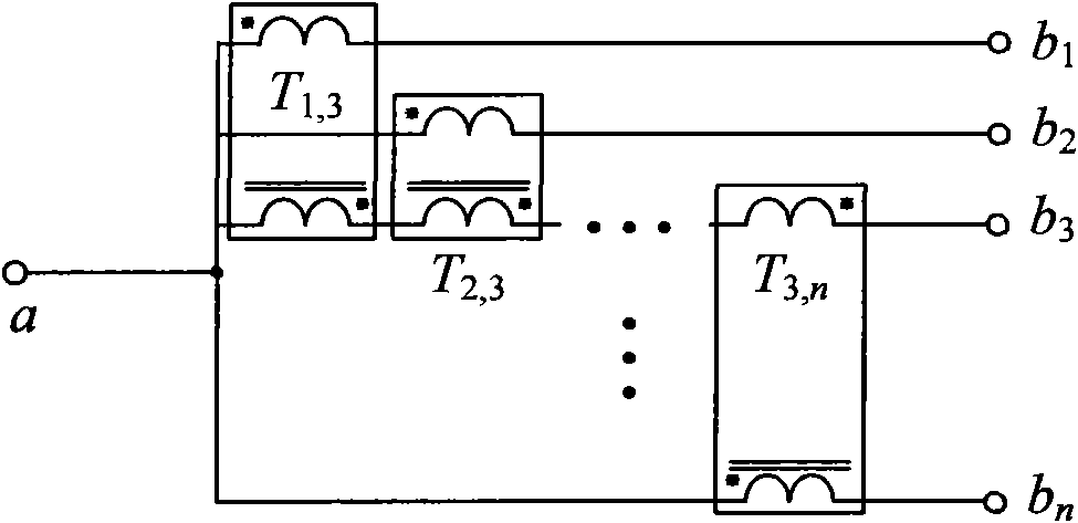
[0021] Embodiment 1 of the present invention, with reference to appended figure 1 , is a schematic diagram of a central reverse coupling transformer. The transformer winding of branch 3 is split into n-1 parts, and n-1 reverse coupling transformers are formed with the remaining n-1 phase branches. "*" is the same name of the two-phase winding of the same reverse coupling transformer end.

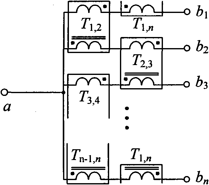
[0022] Embodiment 2 of the present invention, with reference to appended figure 2 , is a schematic diagram of the end-to-end closed reverse coupling transformer. Each phase winding is divided into two windings connected in series, and the adjacent two-phase windings form a reverse coupling transformer, which are combined in turn to form a closed-loop connection. T...


PUM


Abstract

The invention discloses a coupling inductor applicable to a multi-phase interleaved parallel converter. A structure of the coupling conductor is mainly formed by combining backcoupling transformers consisting of two phases of windings and an energy storage inductor; for an n-phase interleaved parallel converter, the quantity of the backcoupling transformers is n-1 or n or n(n-1)/2, and the connection relation of the backcoupling transformers is a central type or a head-tail closure type or a two-two combination type respectively; and the energy storage inductor is serially connected with at least one phase of the winding in the backcoupling transformers, the winding quantity of the energy storage inductor is between 1 and n, and various phases of the windings of the energy storage inductor are independent from each other or are subjected to forward coupling. The coupling inductor ensures that an energy storage function and a filtering function are borne by the energy storage inductor and the backcoupling transformers respectively by splitting the energy storage function and the filtering function, can effectively avoid the intrinsic contradiction between the energy storage function and the filtering function in a multi-magnetic circuit magnetic core, further reduce the loss and volume of magnetic components, improve the power density, the conversion efficiency and the output dynamic performance of the converter, and is suitable for the multi-phase interleaved parallel converters.

Description

technical field [0001] The invention relates to a coupled inductor suitable for use in multi-phase interleaved parallel converters, belonging to the field of inductors or voltage conversion. Background technique [0002] In a switching power supply, the filter inductor plays a very important role in filtering and energy storage, but there is a contradictory relationship between these two functions: under the premise of ensuring that the number of turns of the filter inductor and the maximum The greater the average current passing, the greater the reluctance of the magnetic core is required, that is, the smaller the inductance value of the filter inductance, and to improve the filtering ability, the greater the inductance value of the filter inductance is required. In order to alleviate these two contradictions, the method of keeping the reluctance constant and increasing the effective permeable area, that is, increasing the volume of the magnetic parts, is usually adopted. ...

Claims


Application Information

Patent Timeline
IPC IPC(8): H01F38/14H01F30/06H01F27/28H02M3/315H02M1/08
Inventor 徐立刚陈乾宏任小永
Owner NANJING UNIV OF AERONAUTICS & ASTRONAUTICS
Why Eureka
Try Eureka