Surface mounting fuse protector and manufacturing method thereof

A surface mount and fuse technology, which is applied in the field of surface mount fuses and their manufacturing, can solve the problems of low production efficiency, reducing the consistency of fuse fusing characteristics, etc.

Active Publication Date: 2009-10-28
AEM COMPONENTS (SUZHOU) CO LTD
View PDF19 Cites 28 Cited by
  • Summary
  • Abstract
  • Description
  • Claims
  • Application Information

AI Technical Summary

Problems solved by technology

The formation of this low-melting point alloy reduces the consistency of the blowing characteristics of the fuse
In addition, this kind of fuse needs to be assembled one by one, and the production efficiency is low

Method used


Image

  • Surface mounting fuse protector and manufacturing method thereof
  • Surface mounting fuse protector and manufacturing method thereof
  • Surface mounting fuse protector and manufacturing method thereof

Examples


Embodiment 1

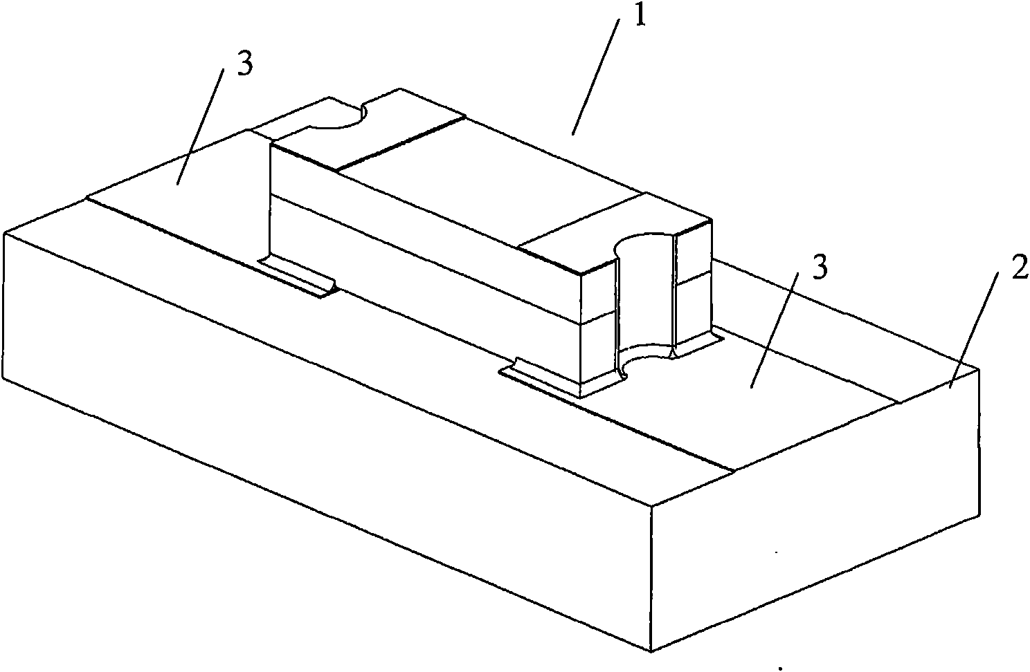
[0062] Manufacturing the above-mentioned fuse 1 of the present invention may include the following steps.

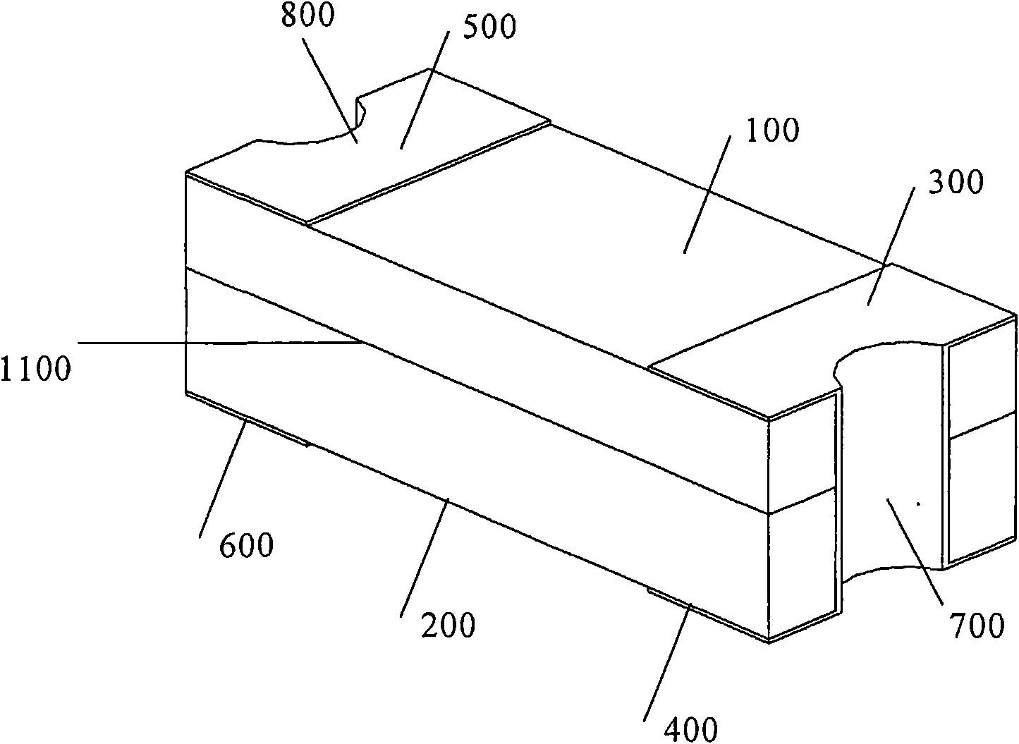
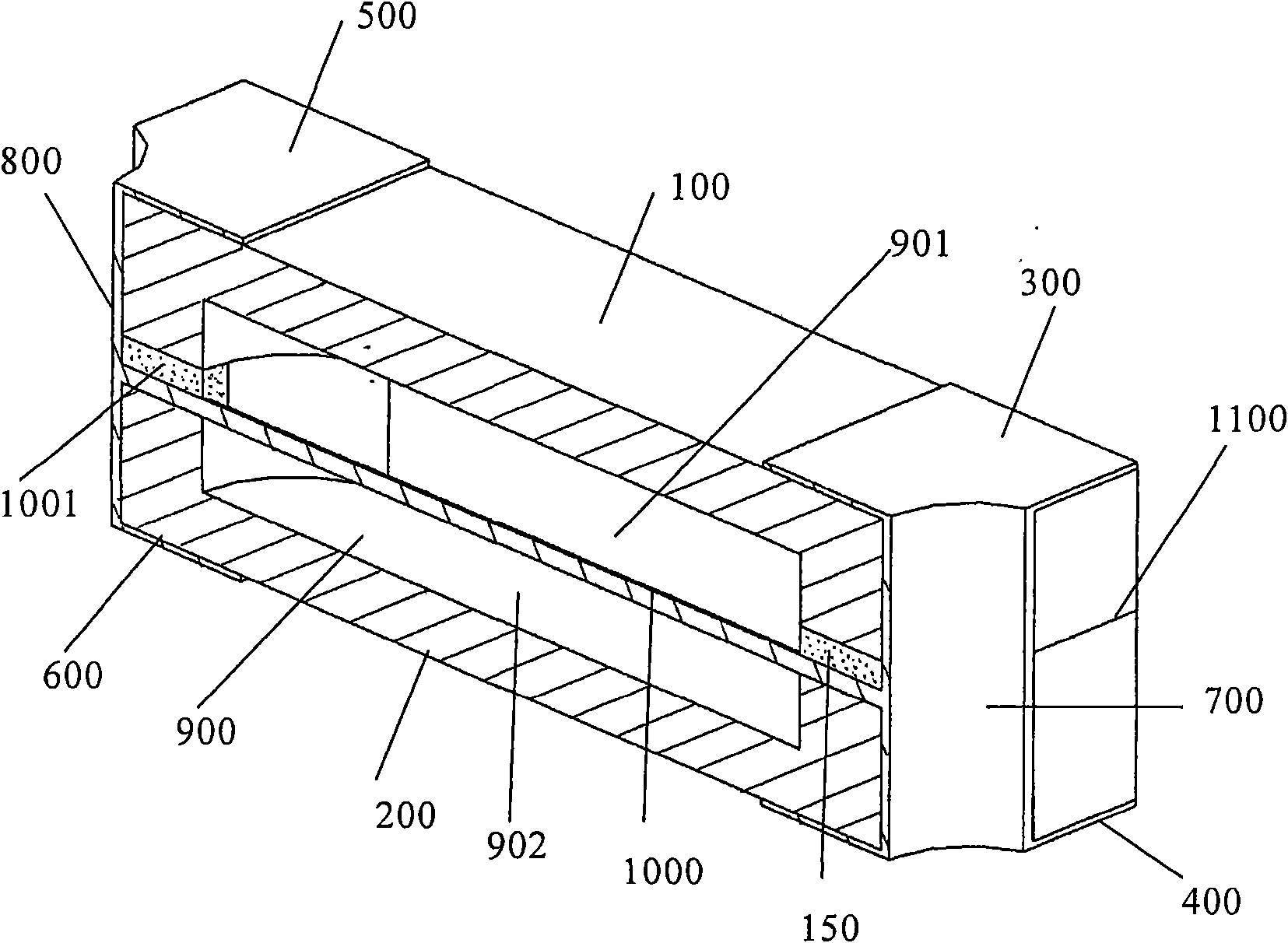
[0063] Prepare two insulating boards (polymer material boards such as thermoplastic or thermosetting plastics) as the upper and lower substrates 100, 200, and attach copper foil to both ends of one side of the substrate 100, 200 to form terminal electrodes 300, 500, 400, 600. It is also possible to prepare a substrate with copper foil attached to one side, and then use electrochemical corrosion or mechanical processing to remove part of the copper foil to form separate terminal electrodes 300, 500, 400, 600 at both ends. Certainly, the terminal electrodes 300, 500, 400, 600 may also be formed of other conductive materials.

[0064] On the other sides of the upper and lower substrates 100, 200 where terminal electrodes are not formed, corresponding concave cavities 901, 902 are machined by mechanical means, such as milling, punching and the like.

[0065] On the side of...

Embodiment 2

[0071] see Figure 5-12 , multiple fuses 1 above can be processed at one time through two larger substrate materials.

[0072] The substrate material can be a single-sided printed circuit board substrate with a wide range of sources and low cost. This substrate is covered with a layer of copper foil on a polymer material. Of course, double-sided printed circuit boards can also be used after removing the copper foil on one side. Other thermoplastic or thermosetting plastics coated with copper foil or other layers of conductive material are also included in the available substrate materials.

[0073] see Figure 5 , 6 The copper foil 10 covered on the polymer material 11 of the substrate material is made into a terminal electrode pattern corresponding to the terminal electrode by means of electrochemical corrosion or mechanical processing. The terminal electrode pattern can be, for example, as Figure 5 , 6 Shown in parallel strips, other suitable shapes are possible as d...


PUM


Abstract

The invention provides a surface mounting fuse protector and a manufacturing method thereof. The surface mounting fuse protector comprises an upper base plate, a lower base plate and a fuse wire, wherein one end of the outer side of the upper base plate is provided with a first end electrode, the other end of the same is provided with a second end electrode, and the middle of the inner side of the upper base plate is provided with a first recessed cavity; one end of the outer side of the lower base plate is provided with a third end electrode corresponding to the first end electrode, the other end of the same is provided with a fourth end electrode corresponding to the second end electrode, the middle of the inner side of the lower base plate is provided with a second recessed cavity corresponding to the first recessed cavity, and the first recessed cavity and the second recessed cavity together form a cavity; the fuse wire is clamped between the upper base plate and the lower base plate, a part of the fuse wire is suspended in the cavity, the first end electrode and the third end electrode are electrically connected with one end of the fuse wire, and the second end electrode and the fourth end electrode are electrically connected with the other end of the fuse wire. The wire suspending type surface mounting fuse protector reduces the heat transfer rate of the fuse wire at the periphery, is simple in structure and has the low stress of the fuse wire.

Description

technical field [0001] The invention relates to a surface mounting fuse and a manufacturing method thereof, in particular to a suspended wire type small surface mounting fuse and a manufacturing method thereof. Background technique [0002] Currently, printed circuit boards are increasingly used in various electrical and electronic devices. Circuits formed on these printed circuit boards generally require overcurrent protection. One way to provide this overcurrent protection is to use small surface mount fuses mounted on the printed circuit board. [0003] At present, there are two main types of small surface mount fuses. One is the solid device type (Solid Body), and the other is the suspended wire type (Wire-In-Air). [0004] The solid device type fuse is characterized in that the fuse (fuse element) is embedded in the surrounding supporting or arc-extinguishing material to form a solid structure. Fuses of the solid state device type are described in the US patents lis...

Claims


Application Information

Patent Timeline
Patent Type & Authority Applications(China)
IPC IPC(8): H01H85/046H01H85/143H01H69/02
Inventor 李向明杨晓鹏汪立无
Owner AEM COMPONENTS (SUZHOU) CO LTD
Why Eureka
Try Eureka