Multi-frequency folded coil antenna

A loop antenna and loop technology, applied in loop antennas, antennas, antenna supports/mounting devices, etc., can solve the problems of not being able to directly apply mobile phone antennas, increase bandwidth, etc.

Inactive Publication Date: 2009-10-28
ACER INC
View PDF1 Cites 16 Cited by
  • Summary
  • Abstract
  • Description
  • Claims
  • Application Information

AI Technical Summary

Problems solved by technology

However, when the size of the loop antenna is greatly reduced, although the low-frequency band can cover the operation of GSM850 or GSM900, it is difficult to cover the dual-frequency operation of GSM850 / 900 at the same time. Therefore, it is necessary to seek a technology to increase the bandwidth. Related technologies such as US Patent No. US 7,242,364 No. B2 "Dual-Resonant Antenna (Dual-Resonant Antenna)", which discloses a technology that uses a matching circuit for a built-in mobile phone antenna operating in a mobile communication system, enabling a single resonance mode to have dual-resonance characteristics to achieve increased The effect of bandwidth, but this technology only discloses the application method of the built-in mobile phone antenna for single-frequency operation, and cannot be directly applied to dual-band (such as 900MHz and 1800MHz) mobile phone antennas

Method used


Image

  • Multi-frequency folded coil antenna
  • Multi-frequency folded coil antenna
  • Multi-frequency folded coil antenna

Examples


Embodiment Construction

[0022] First, the main symbols in the drawings are explained:

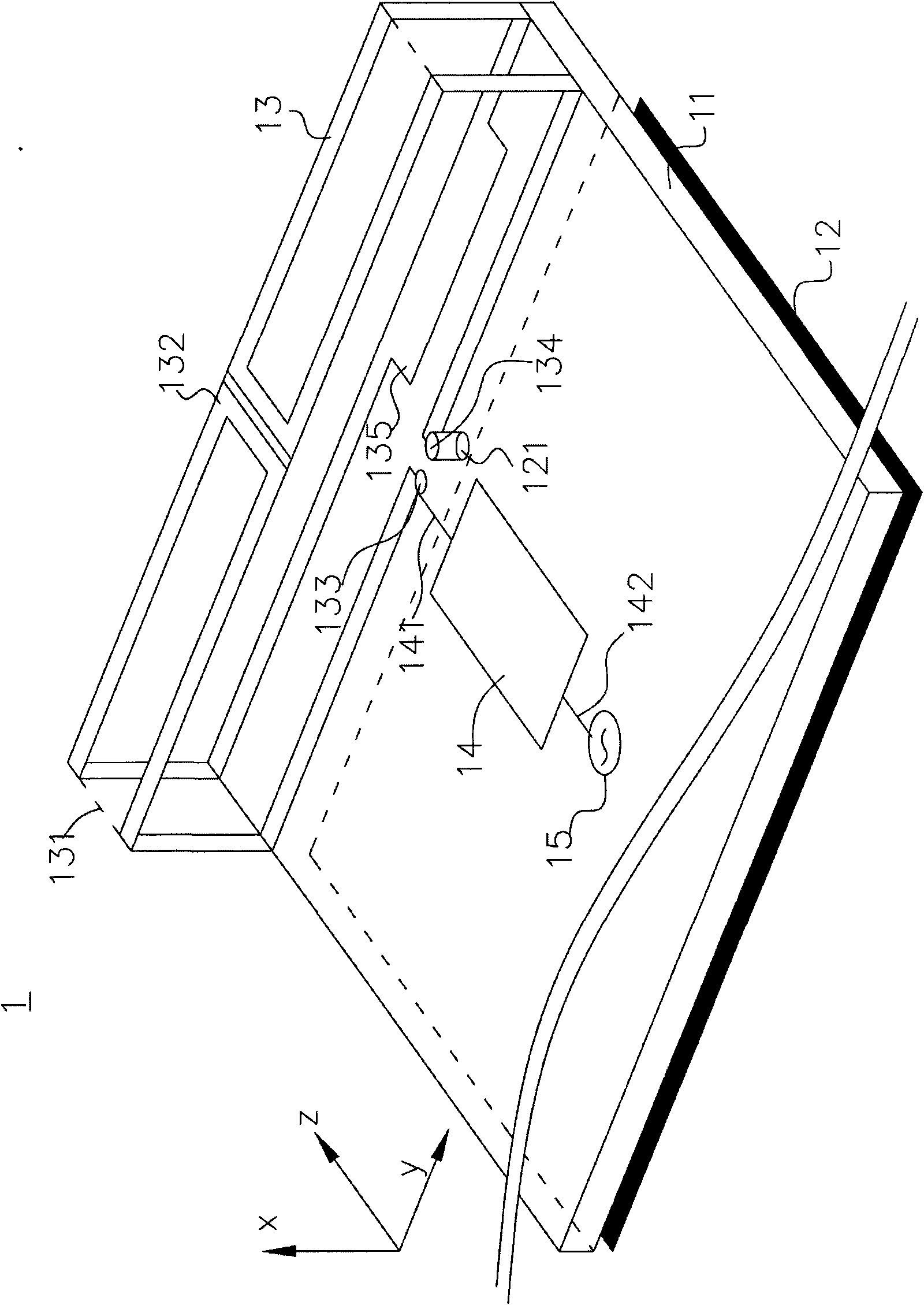
[0023] 1 is the first main embodiment of the antenna of the present invention;

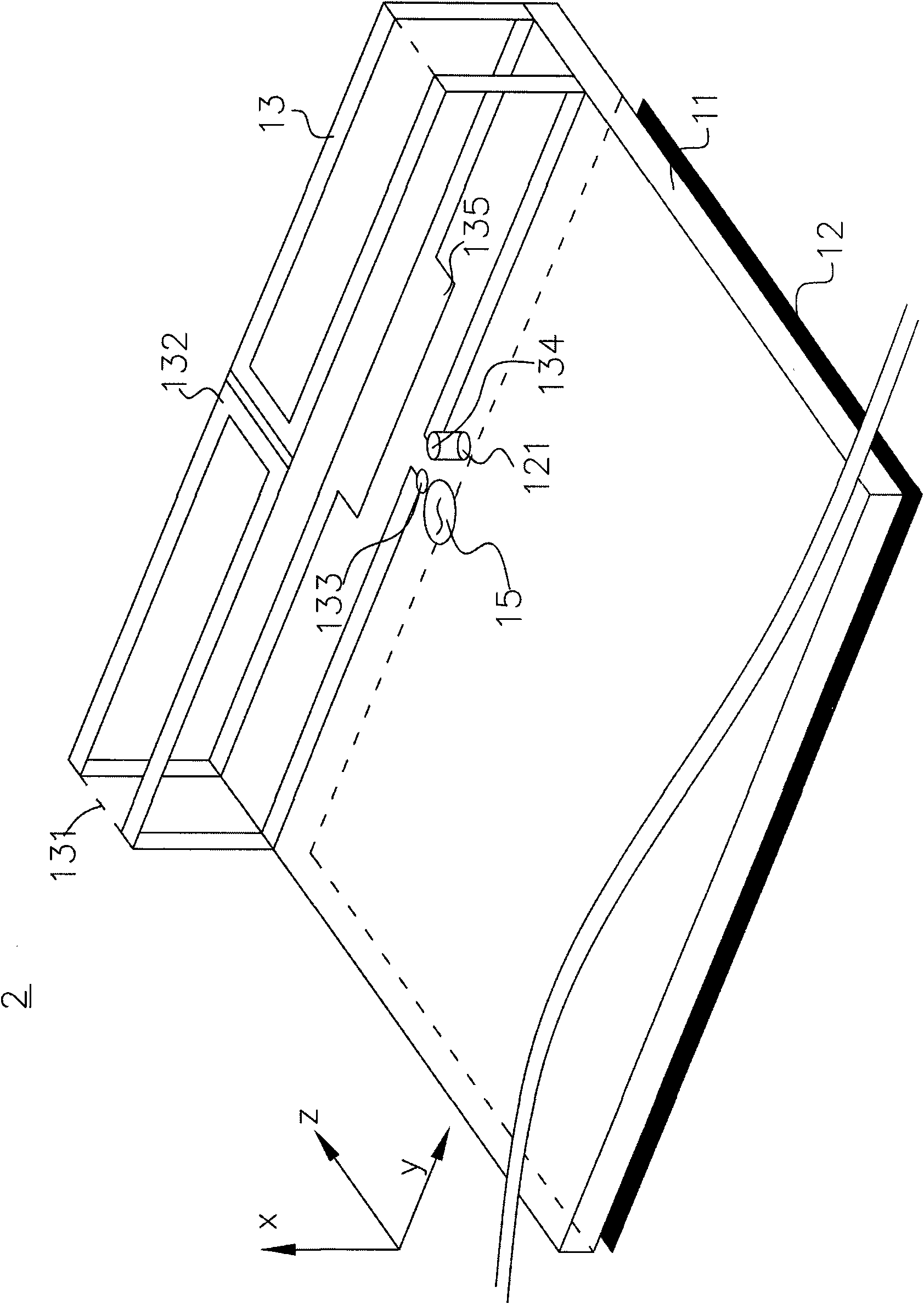
[0024] 2 is the second main embodiment of the antenna of the present invention;

[0025] 7 is the first other embodiment of the antenna of the present invention;

[0026] 8 is the second other embodiment of the antenna of the present invention;

[0027] 9 is the third other embodiment of the antenna of the present invention;

[0028] 10 is the fourth other embodiment of the antenna of the present invention;

[0029] 11 is a dielectric substrate;

[0030] 12 is the ground plane;

[0031] 121 is a grounding point;

[0032] 13 is the radiation department;

[0033] 131 is a supporting medium;

[0034] 132, 732, 832 are annular metal wires;

[0035] 133 is the feed-in end of the ring wire;

[0036] 134 is the ground terminal of the ring metal wire;

[0037] 135 is a metal sheet;

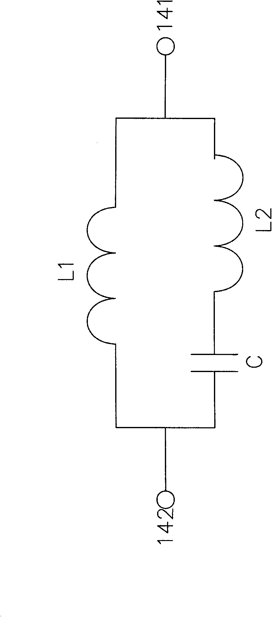
[0038] 14 is a matching circuit;

[0039] 141 ...


PUM


Abstract

The invention relates to a multi-frequency folded coil antenna comprising a medium base plate, a grounding surface, a radiation part and a matching circuit, wherein the grounding surface is provided with a grounding point and is positioned on the medium base plate; the radiation part comprises a support medium, an annular metal wire and a regulating metal sheet, wherein the length of the annular metal wire of the radiation part is about half of the wave length of the lowest resonance frequency of the multi-frequency folded coil antenna, the annular metal wire is also provided with a feed-in end and a grounding end, wherein the grounding end is electrically connected with the grounding point of the grounding surface, the annular metal wire is folded into a spatial structure and supported bythe support medium, and the regulating metal sheet of the radiation part is electrically connected with the annular metal wire; the matching circuit is positioned on the medium base plate, one end of the matching circuit is electrically connected with the feed-in end of the annular metal wire of the radiation part, and the other end is connected with a signal source.

Description

technical field [0001] The invention relates to a loop antenna, in particular to a multi-frequency folded loop antenna suitable for built-in mobile phones. Background technique [0002] With the rapid development of wireless communication, antennas play a more important role in wireless communication products. Especially under the trend of light, thin, short and small, the size of the antenna, especially its height, will affect the value of a product. However, taking the built-in mobile phone antenna as an example, as far as the actual needs of the industry are concerned, the space for placing the antenna inside the mobile phone is becoming more and more limited, but an antenna that can support multi-band operation is a necessary trend. We found that the loop antenna is more suitable for use as a built-in mobile phone antenna than the traditional monopole or panel antenna. The width is small and significantly reduced, which is different from the characteristics of tradition...

Claims


Application Information

Patent Timeline
Patent Type & Authority Applications(China)
IPC IPC(8): H01Q1/24H01Q5/00H01Q7/00H01Q5/10H01Q5/20H01Q5/335H01Q5/50
Inventor 郗韵文翁金辂
Owner ACER INC
Why Eureka
Try Eureka