A bearing and method for transferring forces through a bearing of a wind turbine

A wind turbine and force transmission technology, applied in the direction of bearings, bearings, ball bearings and other directions of rotating motion, can solve problems such as increasing bearing degradation and shortening service life, and achieve the effect of reducing friction, reducing production and installation costs, and simplifying structure

Inactive Publication Date: 2009-10-28
VESTAS WIND SYST AS
View PDF1 Cites 11 Cited by
  • Summary
  • Abstract
  • Description
  • Claims
  • Application Information

AI Technical Summary

Problems solved by technology

[0008] The disadvantage of the described bearings is that for large-scale wind turbine bearings carrying high loads, the inertial forces between adjacent roller elements lead to increased degradation of the bearing and shorten its service life

Method used


Image

  • A bearing and method for transferring forces through a bearing of a wind turbine
  • A bearing and method for transferring forces through a bearing of a wind turbine
  • A bearing and method for transferring forces through a bearing of a wind turbine

Examples


Embodiment Construction

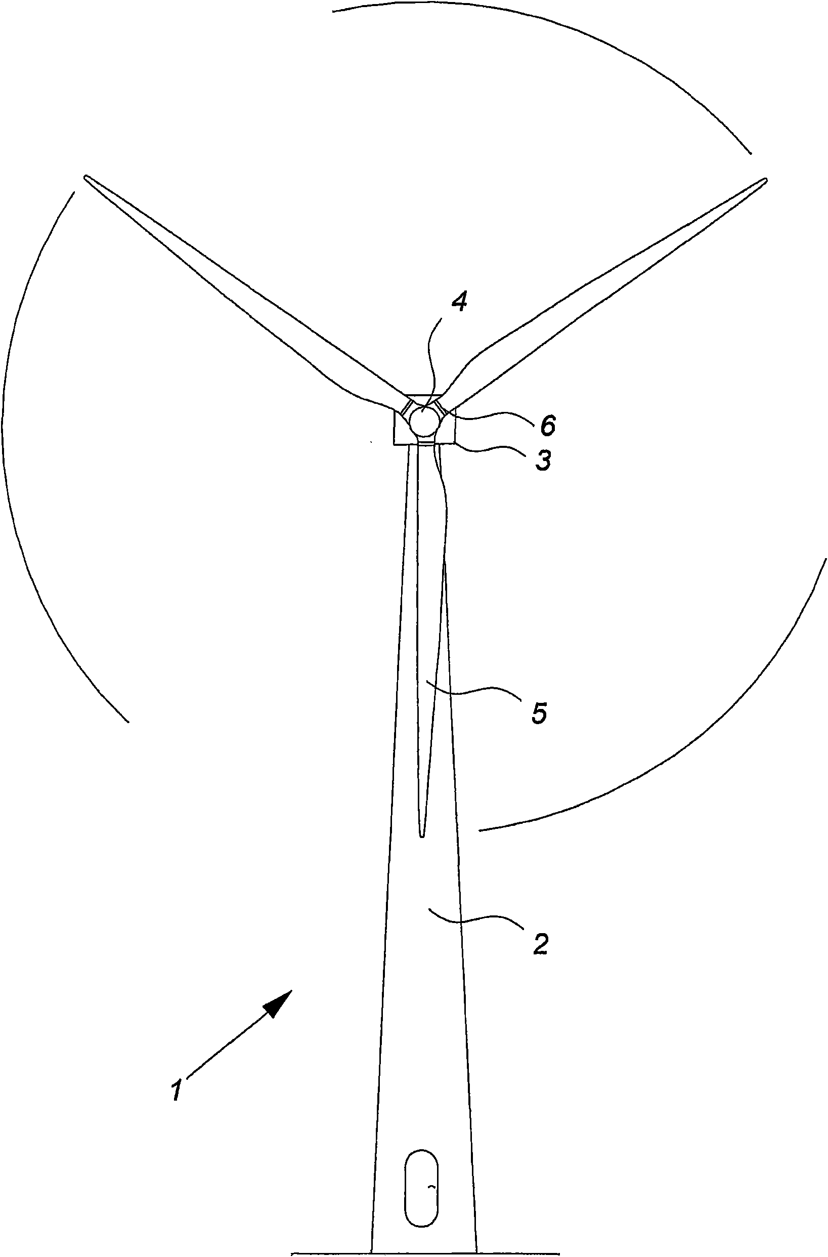
[0041] figure 1 A modern wind turbine 1 is shown with a tower 2 and a wind turbine nacelle 3 on top of the tower 2 .

[0042] A wind turbine rotor is connected to the hub 4 via a pitch mechanism 6, said wind turbine rotor comprising at least one blade, for example as figure 1Three wind turbine blades 5 are shown. Each pitch mechanism includes a blade bearing and a separate pitch actuator that enables the blade to pitch. The pitch change process is controlled by the pitch controller.

[0043] Such as figure 1 As shown, wind above a certain level will actuate the rotor and cause the rotor to rotate in a direction substantially perpendicular to the wind direction. The rotational motion is converted into electrical power, which is typically supplied to a utility grid, as known to those skilled in the art.

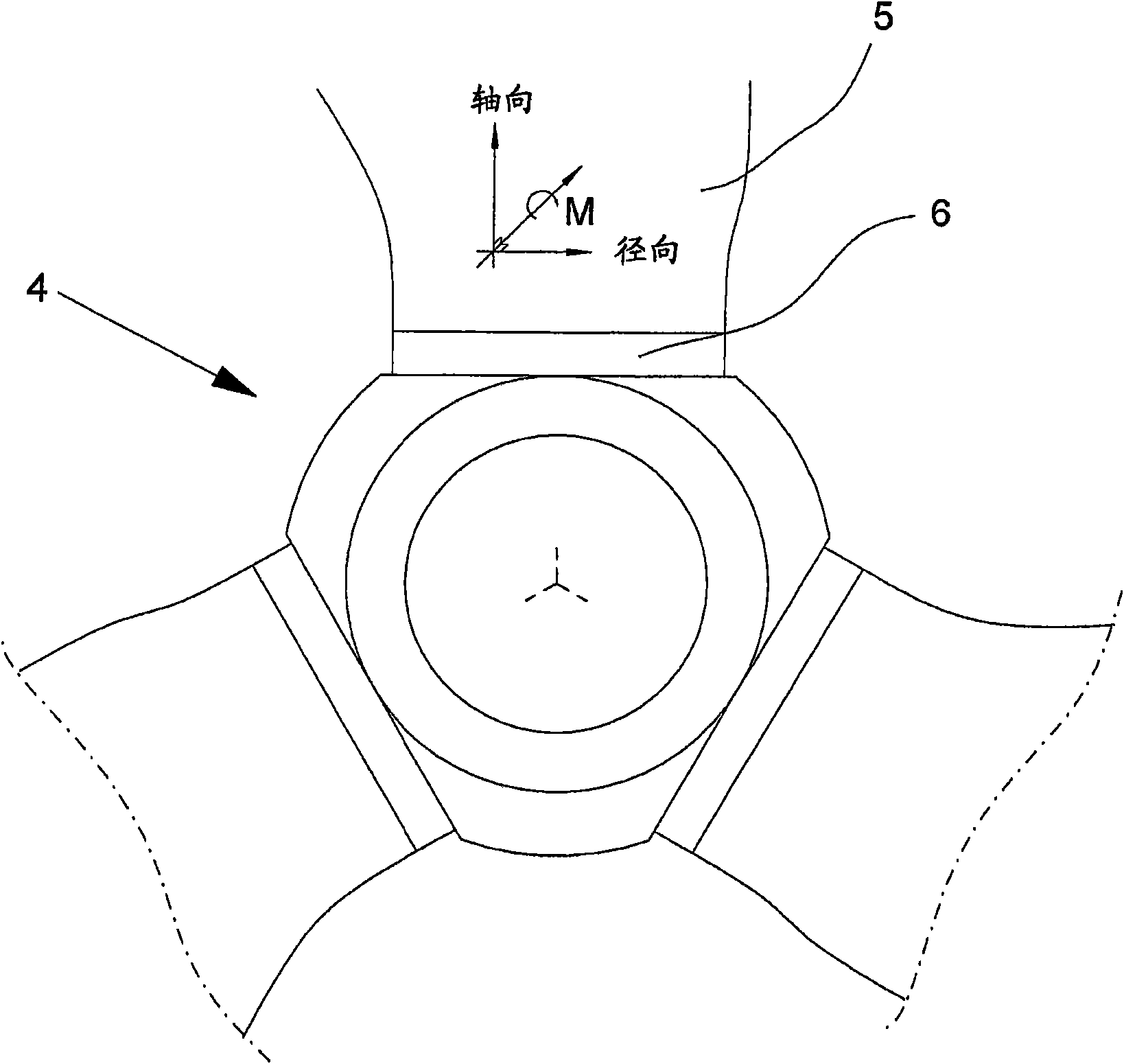
[0044] figure 2 A front view of the wind turbine hub 4 is shown. The wind turbine rotor blade 5 is connected to the hub 4 through a pitch mechanism 6, and the pitch ...


PUM


Abstract

The invention relates to a bearing with at least one row of rolling elements, where at least one of said at least one row of rolling elements comprise a plurality of first rolling elements adapted for substantially transferring axial forces, and a plurality of second rolling elements adapted for substantially transferring radial forces. To minimize friction, at least one of said at least one row of rolling elements comprises means for separating rolling elements, wherein said means for separating rolling elements comprises one or more cages for retaining said rolling elements, where said one or more cages comprise a pocket adapted for allowing the rolling element to be displaced in the longitudinal direction of said row of elements. The invention also relates to a method for transferring forces through a bearing of a wind turbine.

Description

technical field [0001] The invention relates to a bearing according to the preamble of claim 1 and to a method for transmitting forces via a bearing of a wind turbine. Background technique [0002] Typically, larger wind turbines use specially constructed four-point contact ball bearings or crossed roller bearings for use in wind turbines. This is especially true for pitch and yaw bearings. [0003] The balls and / or rollers of the bearings carry the load applied to their support structure, including the bearing rings, and provide low friction motion about the bearing's axial axis of rotation. [0004] Bearings of the type described above have distinct load paths for the rolling elements and can carry simultaneous moment and radial and axial loads. Hardened surfaces on the inner and outer rings provide the points of contact between the stationary and moving elements of the bearing. [0005] German patent application DE19510182A1 discloses a yaw roller bearing used in a win...

Claims


Application Information

Patent Timeline
Patent Type & Authority Applications(China)
IPC IPC(8): F16C19/14F16C19/34F16C19/54F16C33/38F16C33/46F16C33/51F03D11/00
CPCF16C33/46F16C19/362F05B2240/52F05B2250/41Y02E10/726F05B2250/40F05B2240/54F16C33/51F16C19/18F16C33/3818F16C2300/14Y02E10/722Y02E10/72F16C19/381F16C19/505F16C33/3706F03D11/0008F16C19/38F16C2360/31F03D80/70
Inventor J·L·安诺生
Owner VESTAS WIND SYST AS
Why Eureka
Try Eureka