Acoustic generator after total laryngectomy

A sound generator and laryngeal disease technology, applied in the field of medical devices, can solve the problems of difficult dialogue and communication, unclear pronunciation, increased burden and multiple pains, etc., so as to reduce pain and cost burden, and the installation method is simple and easy to implement and popularized. The effect of the application foreground

Inactive Publication Date: 2009-11-04
黄祥顺
View PDF0 Cites 0 Cited by
  • Summary
  • Abstract
  • Description
  • Claims
  • Application Information

AI Technical Summary

Problems solved by technology

[0003] 1. Since there is a block and a tail-like handle at the end of the airway fistula of the sound transmission tube, and the tracheal fistula after laryngectomy is relatively small, the block and the handle occupy a large and long space. General anesthesia is required before the installation of the artificial vocalizer for an operation to expand the tracheal fistula. Two months later, an anesthesia operation for the fistula tract with an acoustic tube is required. After one week, a doctor needs to go to the hospital to install the artificial vocalizer. Used on patients, causing troubles to patients, increasing burden and suffering many times
[0004] 2. Because the duckbill-shaped valve protrudes too far out of the esophageal opening, not only the user is blocked from eating and swallowing food, but also the flexibility of the valve decreases after a period of use, and the valve does not work for a short period of time (half a year). It is necessary to go to the installation hospital to replace the artificial valve. sounder
[0005] 3. The inner diameter of the sound transmission tube is less than 2.5mm, the channel is small, and the diameter of the air inlet hole on the tube wall is less than 2.5mm, the opening is small, which affects the quality of the sound, the sound volume is light and small, the pronunciation is not clear, the speech is not smooth, and it is not easy to communicate with others Dialogue
[0006] Other artificial vocalizers, such as electronic laryngeal vocalizers and artificial laryngeal speech vocalizers, have complex structures, large volumes, large manufacturing difficulties, inconvenient installation and use, and high costs, which are unfavorable for popularization and application.

Method used


Image

  • Acoustic generator after total laryngectomy

Examples


Embodiment Construction

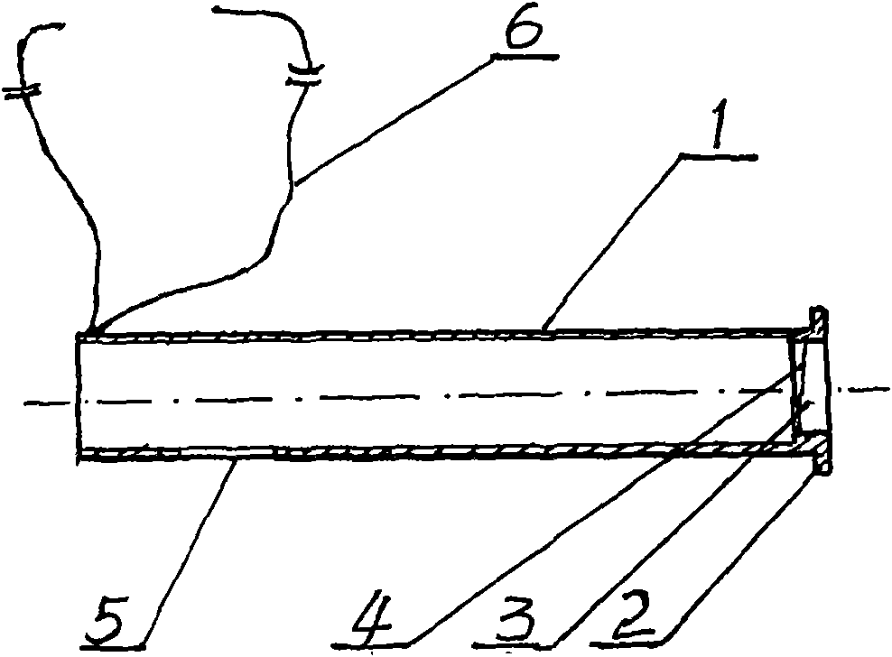
[0013] With reference to the accompanying drawings and embodiments, the specific structure and installation method of the sound generator after total laryngectomy of the present invention are further described, and its characteristics and advantages are more clear.

[0014] For an example of the sound generator after total laryngectomy of the present invention, see figure 1 , Its structure includes: a sounding tube 1, a ring-shaped hanger 2 is provided at the left end of the sounding tube 1, a concave platform 3 is set in the pipe end inside the ring-shaped hanger 2, and a membrane valve 4 is embedded on the concave platform 3. The right end of 1 is connected with a proper length of medical wire as a harness 6, and an air inlet 5 is opened on the pipe wall opposite to the connection point of the harness 6. The wall thickness of the sound tube 1 is appropriately reduced without affecting the strength. The inner diameter of the sound tube 1 is greater than 2.5mm, preferably 2.5-3.5m...


PUM


Abstract

The invention relates to an acoustic generator after total laryngectomy. The acoustic generator is characterized in that a diaphragm valve is arranged on a concave platform in a tubular end inside a bracket on one end of the acoustic generator; the other end of an acoustic tube opposite to an air inlet is provided with a string; when the acoustic generator is mounted, local anaesthesia is adopted, fistulous tract is pricked by a cone, and the acoustic tube is inserted into the fistulous tract once, and the string is bound on a close position of a patient. Compared with the prior artificial acoustic generator, the acoustic generator has significant advantages of simple structure, reliable performance, improved tone quality, prolonged service life, simple and easy installation, self-service change realization for the patient, pains and cost reduction for the patient and the like.

Description

Technical field [0001] The invention belongs to the field of medical equipment, and relates to an artificial sound generator, in particular to a sound generator after total laryngectomy. Background technique [0002] There are many patients suffering from laryngeal diseases. After clinical surgery, especially after total resection surgery, they cannot speak and need to install artificial sound generators. An existing artificial sound generator used in clinical practice has a hanging piece on the peripheral edge of one end of the corresponding esophagus of the sound tube, and a duckbill valve is connected to the outside of the sound tube, and the corresponding tracheal fistula of the sound tube A baffle is arranged on the periphery of the mouth end and a tail-shaped pull handle is connected on the edge of the baffle, so that the artificial sound generator for fire protection can be accidentally entered into the body. An air inlet hole is also opened on the pipe wall inside the baf...

Claims


Application Information

Patent Timeline
Patent Type & Authority Applications(China)
IPC IPC(8): A61F2/20
Inventor 黄祥顺李广伟单铭铭
Owner 黄祥顺
Why Eureka
Try Eureka