Sliding mechanism controlling ladle molten steel casting flow rate

A technology of flow control and sliding mechanism, applied in casting equipment, manufacturing tools, casting melt containers, etc., can solve the problems of high labor intensity, short service life and low production efficiency of workers, so as to reduce labor intensity of workers and improve safety. Use factor, the effect of improving the service life

Inactive Publication Date: 2009-11-04
河南省伯马股份有限公司
View PDF0 Cites 3 Cited by
  • Summary
  • Abstract
  • Description
  • Claims
  • Application Information

AI Technical Summary

Problems solved by technology

[0002] In the process of ladle casting billets, the ladle controls the flow of molten steel mainly by manual sliding mechanism and hydraulic sliding mechanism. Since the continuous casting of steel billets in the ladle is operated at high temperature, the manual sliding mechanism is only suitable for small ladles less than 50t, and the production efficiency is low.
At present, the continuous casting of steel billets larger than 50 tons mainly uses hydraulic sliding mechanisms to control the flow of molten steel. However, the existing hydraulic sliding mechanisms for molten steel flow control generally have unreasonable designs, and the materials of parts are not resistant to high temperatures. Defects such as short life, inaccurate flow control, etc., and high friction between the fixed slide plate and the sliding slide plate of the direct execution part of flow control, often cause a large gap between the slide plates installed in the control mechanism, which increases the occurrence of runaway during continuous casting of molten steel. The probability of steel and steel breakout accidents is not conducive to safe production and cannot meet the needs of the existing ladle continuous casting technology
Moreover, the casting process is a continuous production process. According to the needs of flow control, it is often necessary to replace the slide plate. However, the current ladle steel casting flow control sliding mechanism makes the slide plate replacement operation complicated, which not only seriously affects production efficiency and workers. The labor intensity is high, and it increases the unsafe factors in the production process, which is not conducive to ensuring the safety of people's lives and property

Method used


Image

  • Sliding mechanism controlling ladle molten steel casting flow rate
  • Sliding mechanism controlling ladle molten steel casting flow rate
  • Sliding mechanism controlling ladle molten steel casting flow rate

Examples


Embodiment 1

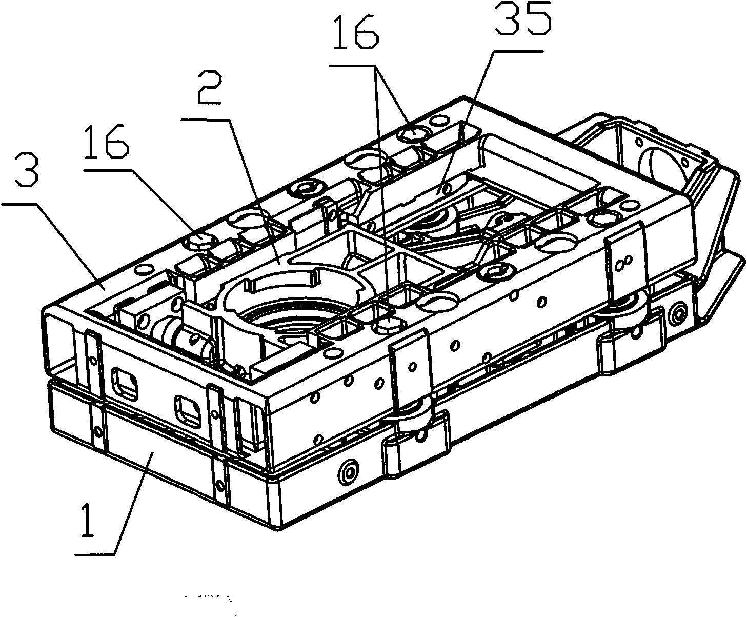
[0020] Embodiment one: see figure 1 , figure 2 , Figure 2-1 , image 3 , Figure 3-1 and Figure 4 . The ladle molten steel casting flow control sliding mechanism of the present invention includes a main frame 1 for installing a fixed slide plate, a slider 2 and a bracket 3 for installing a sliding slide plate, and the slider 2 is matched and slidably installed on the bracket at the lower end of the main frame 1 3, in the carriage frame 31 of the main frame 1 and the bracket 3, corresponding positioning mechanisms are provided on both sides of the docking surface of the main frame 1 and the bracket 3. The main frame 1, the slider 2, and the bracket 3 are connected by elastic tensioning elements. In one piece, four pulleys are respectively installed on both sides of the slider 2 through the wheel shaft 22, and the front end is connected to the external hydraulic cylinder push rod through the cylinder connection pin 25, and two guide rails are arranged symmetrically on bo...

Embodiment 2

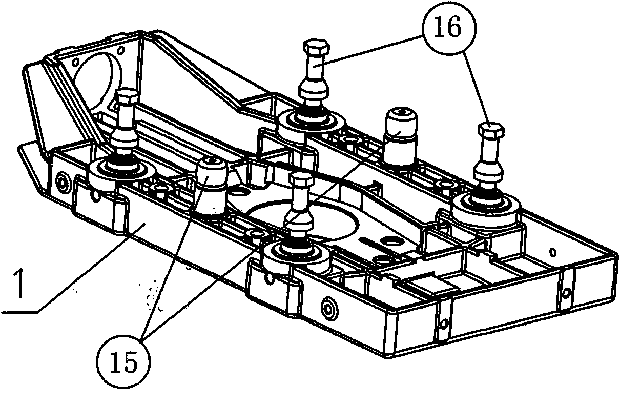
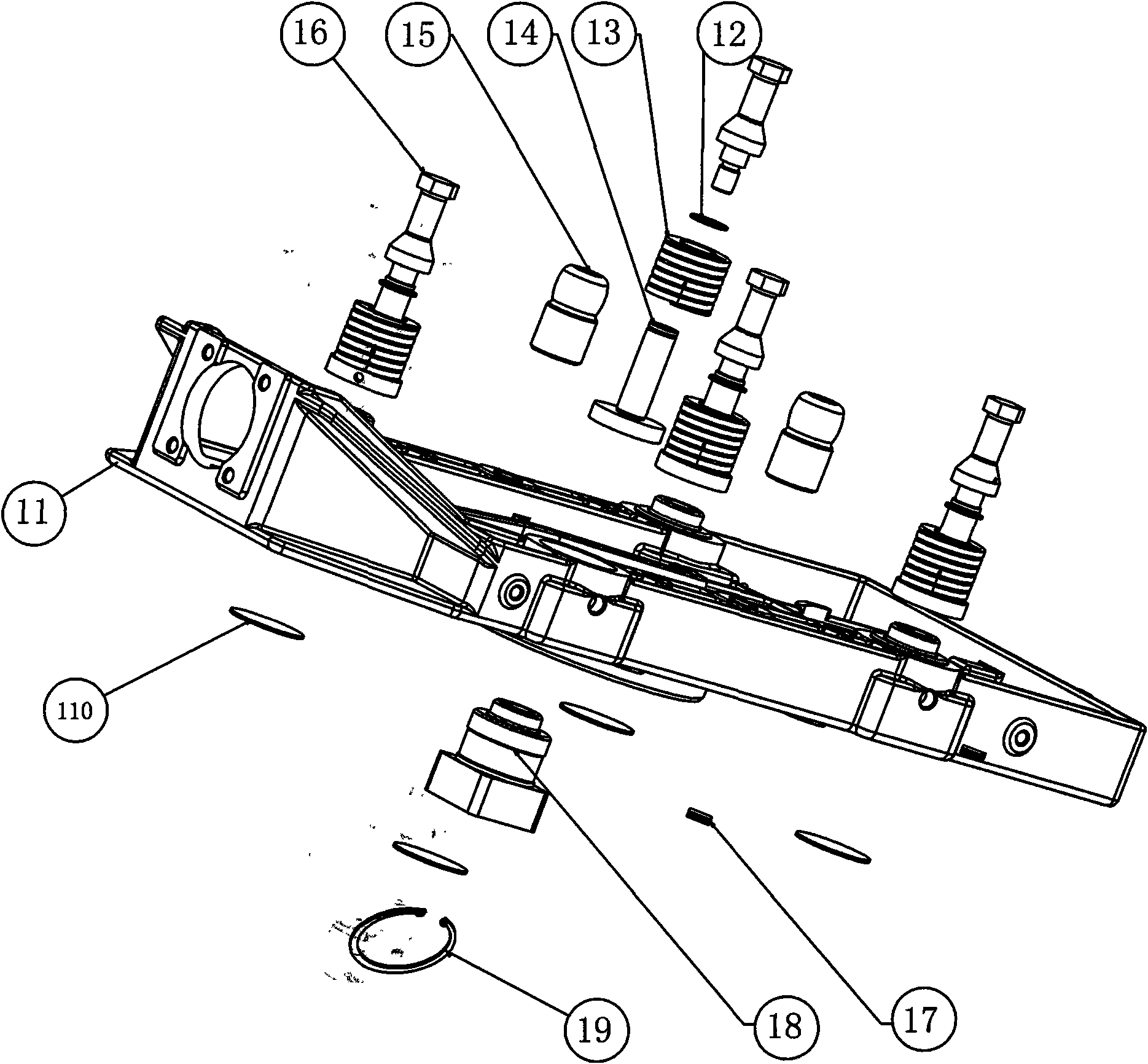
[0023]Embodiment 2: The ladle molten steel casting flow control sliding mechanism of this embodiment is different from Embodiment 1 in that: the main frame 1 includes a support 11, and the positioning mechanisms provided on the docking surfaces of the main frame 1 and the bracket 3 respectively adopt positioning The pin 15 and the pin hole matched with the positioning pin 15, the elastic tensioning element adopts a nickel-based alloy double coil spring 13, and the positions on both sides of the positioning pin 15 are respectively set on the frame body on both sides of the main frame 1 and the bracket 3 joint surface One group, each group of double helical springs 13 will main frame 1, sliding The block 2 and the bracket 3 are connected together, and the elastic tensioning element adopts nickel base alloy double coil spring, so that the gap between the fixed slide plate and the sliding slide plate can be controlled between 0.01-0.04mm.

[0024] The ladle molten steel casting fl...


PUM


Abstract

The invention relates to smelting mechanical equipment. A sliding mechanism controlling ladle molten steel casting flow rate comprises a main frame, a slide block and a support, wherein the slide block is matched with and slide-mounted in a slide block frame of the support on the lower end of the main frame; frame bodies on two sides of the splicing surface of the main frame and the support are respectively provided with positioning mechanism which are matched with each other; the main frame, the slide block and the support are connected into a whole through elastic tension elements; two sides inside the slide block frame of the support are symmetrically provided with two guide rails respectively; a pulley intermediate steel sheet is arranged in the middle of two guide rails on each side; one corresponding end of the guide rails on two sides is provided with a pulley stopper; after the pulley on the other end of the slide block pushed by a pushing rod of an external hydraulic cylinder drops on the position of the pulley stopper, the pulley on the end is just in the pulley intermediate steel sheet. The pin slide board can be changed and operated conveniently, is better matched with the requirement of ladle continuous casting, improves the safety use coefficient and service life of the sliding mechanism, and is beneficial to new technology of steel-making continuous casting.

Description

1. Technical field: [0001] The invention relates to a smelting mechanical equipment, in particular to a flow control sliding mechanism for controlling the flow of molten steel by ladle continuous casting of billets during high temperature smelting. 2. Background technology: [0002] In the process of ladle casting billet, the ladle controls the flow of molten steel mainly by manual sliding mechanism and hydraulic sliding mechanism. Since the continuous casting of steel billet by ladle is operated at high temperature, the manual operation sliding mechanism is only suitable for small ladles less than 50t, and the production efficiency is low. At present, the continuous casting of steel billets larger than 50 tons mainly uses hydraulic sliding mechanisms to control the flow of molten steel. However, the existing hydraulic sliding mechanisms for molten steel flow control generally have unreasonable designs, and the materials of parts are not resistant to high temperatures. Defec...

Claims


Application Information

Patent Timeline
Patent Type & Authority Applications(China)
IPC IPC(8): B22D41/38
Inventor 游佩玉吕培中罗焰王大军陈逢宇牛智旺乔金贵
Owner 河南省伯马股份有限公司
Why Eureka
Try Eureka