Detecting device for measuring difference of relative radius of curvature between sub-lenses of sphere surface spliced telescope

A technology of relative curvature and detection device, which is applied in the direction of measurement device, optical device, optical instrument test, etc., to achieve the effect of high measurement accuracy and high efficiency

Inactive Publication Date: 2009-11-04
CHANGCHUN INST OF OPTICS FINE MECHANICS & PHYSICS CHINESE ACAD OF SCI
View PDF0 Cites 17 Cited by
  • Summary
  • Abstract
  • Description
  • Claims
  • Application Information

AI Technical Summary

Problems solved by technology

[0005] The purpose of the present invention is to propose a detection device for measuring the relative curvature radius difference between the sub-mirrors ...

Method used


Image

  • Detecting device for measuring difference of relative radius of curvature between sub-lenses of sphere surface spliced telescope
  • Detecting device for measuring difference of relative radius of curvature between sub-lenses of sphere surface spliced telescope
  • Detecting device for measuring difference of relative radius of curvature between sub-lenses of sphere surface spliced telescope

Examples


Embodiment Construction

[0017] The detection device of the present invention will be further described in detail in the following embodiments given in conjunction with the accompanying drawings.

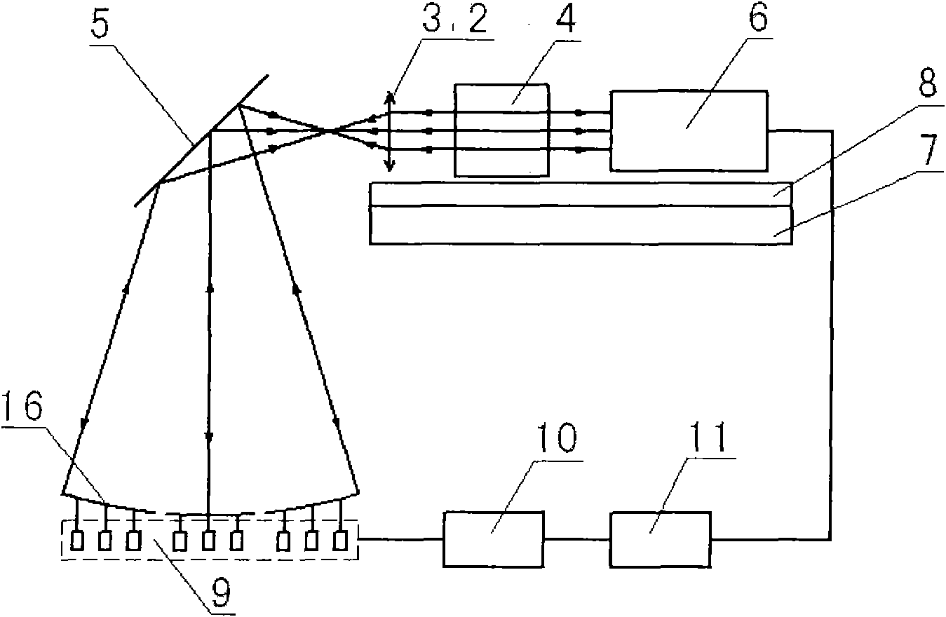
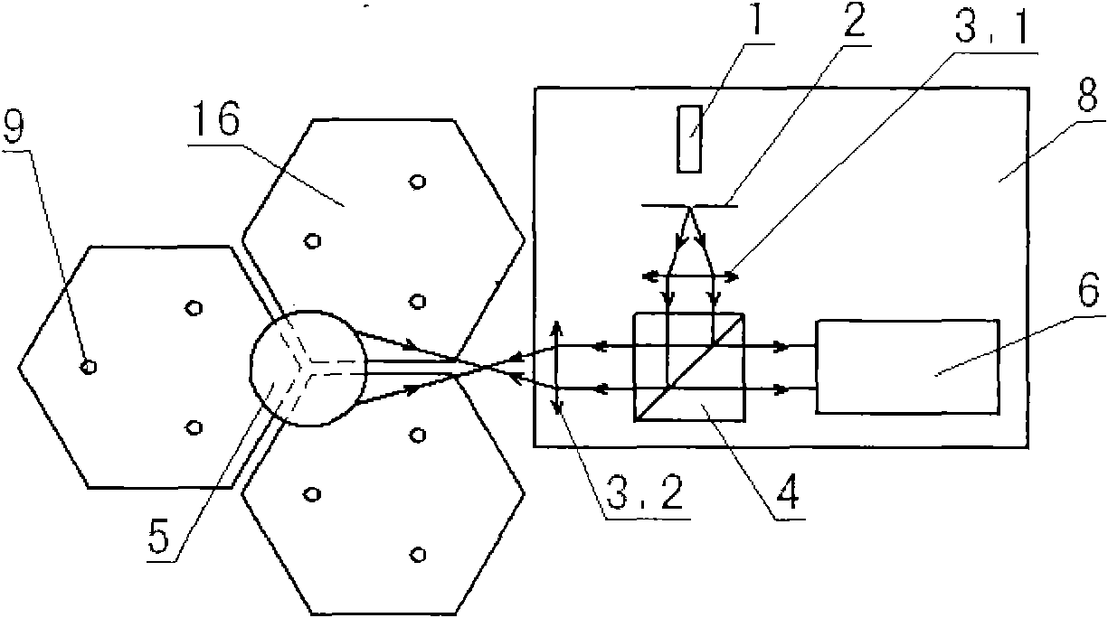
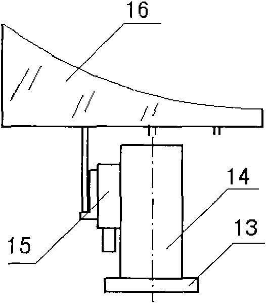
[0018] refer to figure 1 , 2 , a detection device for measuring the relative curvature radius difference between the sub-mirrors of the spherical splicing telescope, including a confocal adjustment system and a spherometer 12, the confocal adjustment system includes a laser source 1, a needle, Hole 2, two collimating lenses 3.1 and 3.2, beam splitting prism 4 and Shack-Hartmann wavefront sensor 6, plane reflector 5, micro-displacement translation stage 9, micro-displacement translation stage controller 10, computer 11; said laser source 1. After passing through the pinhole 2 and the first collimating lens 3.1, the light beam emitted from 1 passes through the second collimating lens 3.2 after being reflected by the dichroic prism 4; The Shack-Hartmann wavefront sensor 6 described above;

[0019] The plane...


PUM


Abstract

The invention relates to a detecting device for measuring the difference of relative radius of curvature between sub-lenses of a sphere surface spliced telescope. The device comprises a confocal adjustment system and a spherometer, wherein the confocal adjustment system comprises a laser source arranged on a mounting plate, a pin hole, two collimating lenses, a dispersion prism, a Shack-Hartmann wave-front sensor, a planar reflector, a micrometric displacement translational platform, a controller of the micrometric displacement translational platform and a computer; after passing through the pin hole and a first collimating lens, light beam emitted by the laser source is emitted out through a second collimating lens after reflection through the dispersion prism; the Shack-Hartmann wave-front sensor is arranged on the other side of the dispersion prism, which is coaxial with the reflecting light path of the dispersion prism; the planar reflector is arranged on the optical axis outside the focal surface of the second collimating lens; and the reflecting light path of the planar reflector is provided with the micrometric displacement translational platform carrying the sub-lens to be measured. The device does not require a standard reference lens, is independent from testing environment, and has high measurement accuracy and high efficiency.

Description

technical field [0001] The invention relates to a spherical mirror optical testing device, in particular to a testing device suitable for measuring the relative curvature radius difference between sub-mirrors of a large spherical splicing telescope. Background technique [0002] With the development of astronomy and aerospace science, scientists urgently need astronomical telescopes with larger apertures to observe more distant, dimmer, and smaller stars or aircraft. The size of the next-generation large-scale ground-based and space-based telescopes has greatly increased, but due to the limitations of rough materials, manufacturing, transportation and (or) launch rockets, the primary mirror of these large telescopes cannot be a whole mirror. The solution of splicing sub-mirrors of blocks to form a large-scale primary mirror is considered to be the most promising option. In order to make each sub-mirror spliced ​​into a continuous curved surface, the radius of curvature of e...

Claims


Application Information

Patent Timeline
IPC IPC(8): G01B11/255G01M11/00
Inventor 林旭东王建立刘欣悦董磊陈宝刚明名李宏壮
Owner CHANGCHUN INST OF OPTICS FINE MECHANICS & PHYSICS CHINESE ACAD OF SCI
Why Eureka
Try Eureka