
Calibration method for six-dimension force sensor calibration device with medium measurement range

A technology of a six-dimensional force sensor and a calibration method, which is applied in the calibration field of a six-dimensional force sensor calibration device with a range, can solve problems such as inability to achieve independent loading, affect calibration accuracy, and difficulty in ensuring accuracy, and achieve convenient calculation of coupling matrix and calibration accuracy High, easy-to-operate effect

Inactive Publication Date: 2009-11-04
ANHUI LONGCOM INTERNET OF THINGS
View PDF1 Cites 18 Cited by
  • Summary
  • Abstract
  • Description
  • Claims
  • Application Information

AI Technical Summary

Problems solved by technology

[0008] First, the calibration device changes the direction of the applied load by adjusting the angle between the load transmission rope and the horizontal plane. When the volume is large or the rope is long, it is difficult to ensure sufficient accuracy by adjusting the angle between the load transmission rope and the horizontal plane. As a result, the applied load has a large direction error, which will directly affect the calibration accuracy; second, the pulley is used to apply the load in the calibration device, and the pulley has friction, which will cause a relatively large loading error, thus affecting the calibration Third, the six-dimensional force sensor in the calibration device applies a compound force / torque, which cannot achieve independent loading of each dimensional force / torque component

Method used


Image

  • Calibration method for six-dimension force sensor calibration device with medium measurement range
  • Calibration method for six-dimension force sensor calibration device with medium measurement range
  • Calibration method for six-dimension force sensor calibration device with medium measurement range

Examples


Embodiment

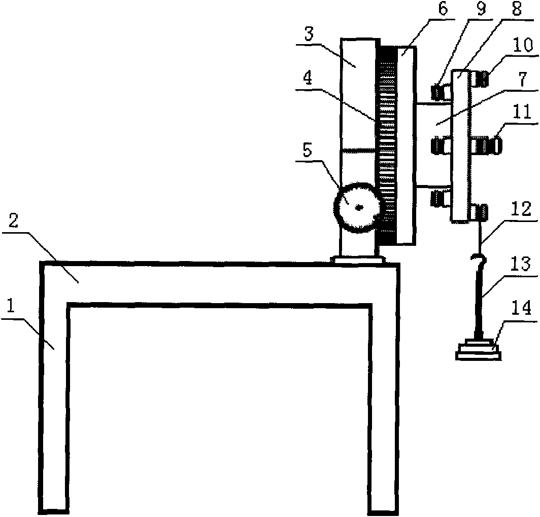
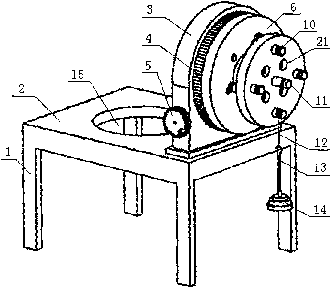
[0080] First, place the workbench support 1 of the six-dimensional force sensor calibration device on a flat ground, place the workbench 2 horizontally on the workbench support 1, and use a spirit level to calibrate the horizontal plane of the workbench 2 to ensure that the workbench 2 is horizontal. The turntable base 3 is vertically installed on one end of the workbench 2, and the turntable base 3, the turntable turntable 4 and the turntable handle 5 form a vertical turntable.

[0081] The loading plate 8 is installed on the six-dimensional force sensor 7 through a set of loading plate sensor mounting holes 21, the six-dimensional force sensor 7 is installed on the adapter plate sensor mounting hole 17 of the adapter plate 6, and the adapter plate 6 passes through a set of The adapter plate mounting hole 16 is installed on the turntable turntable 4 . The suspension hook 13 is hung on the rope 12, the weight 14 is placed on the suspension hook 13, and the rope 12 is hung on ...


PUM


Abstract

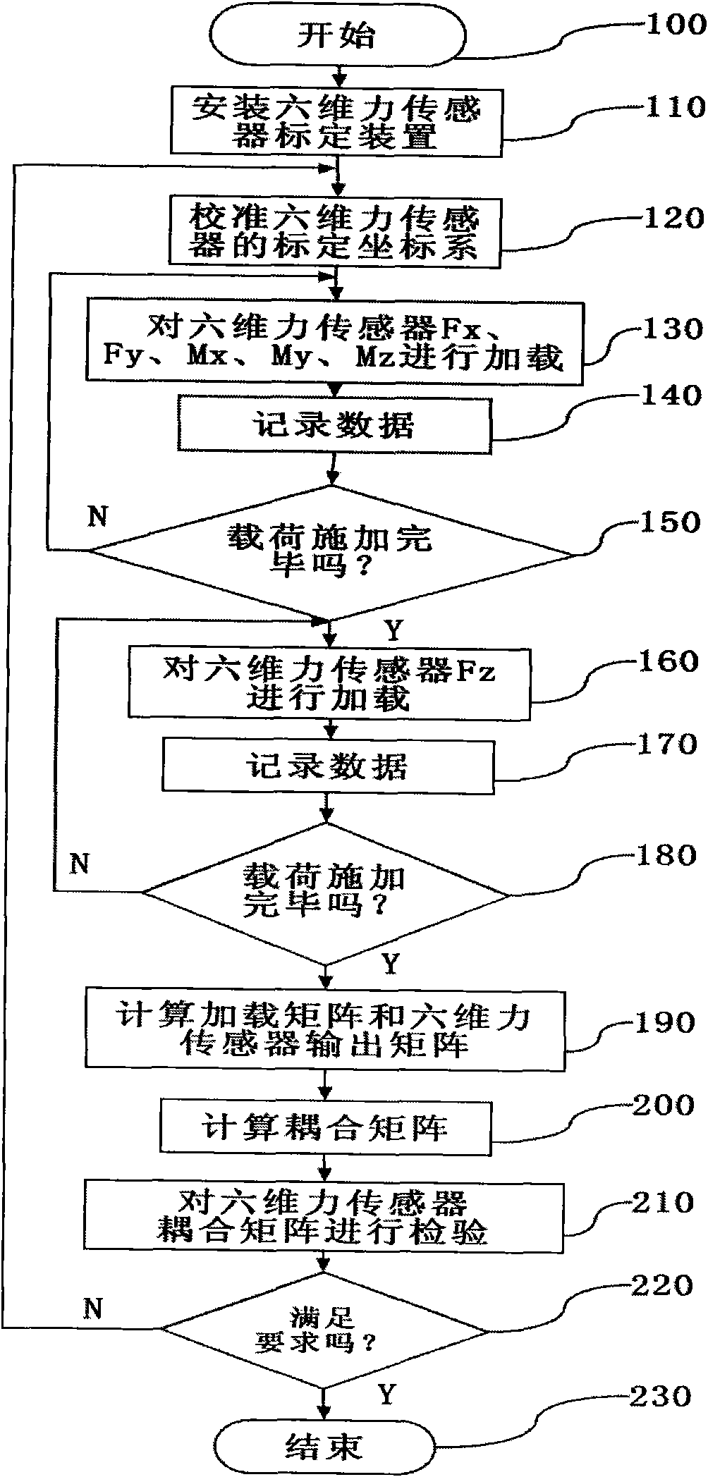
The invention relates to a calibration method for a six-dimension force sensor calibration device with medium measurement range. When in calibration, a rotary table handle is rotated, a rotary table turnplate drives an adapter plate, a six-dimension force sensor and a loading plate to rotate together, wherein the adapter plate, the six-dimension force sensor and the loading plate are arranged on the rotary table turnplate; the rotating angle is controlled by the rotary table handle and is read form scale on the rotary table turnplate; weights with different masses and numbers are respectively hung on a back stress-applying level, a front stress-applying level and a center stress-applying level of the loading plate through drop hangers so as to realize the independent loading and the compound loading of Fx, Fy, Fz, Mx, My and Mz of six force or moment componenets through the change of loading positions, a loading matrix and a corresponding output matrix of the six-dimension force sensor are obtained and are performed the decoupling computation to obtain a coupling matrix, i.e. the calibration of the six-dimension force sensor is completed. The invention has simple structure, convenient operation and high calibration precision, and is suitable to the calibration and the test of the six-dimension force sensor with medium measurement range.

Description

technical field [0001] The invention relates to the field of automation, in particular to a calibration method suitable for a medium-range six-dimensional force sensor calibration device in the sensor field. Background technique [0002] The six-dimensional force sensor can simultaneously detect full force information in three-dimensional space, namely three-dimensional force information (Fx, Fy, Fz) and three-dimensional torque information (Mx, My, Mz), and is mainly used in force and force / position control occasions, such as contour tracking , precision assembly, coordination of both hands, six-dimensional force information detection in the test system, etc. [0003] The measurement accuracy of the sensor is one of the most important performance indicators for evaluating the sensor, and its errors include random errors and systematic errors. For the six-dimensional force sensor, its random error is mainly caused by internal signal processing circuit, quantization error, e...

Claims


Application Information

Patent Timeline
IPC IPC(8): G01L25/00
Inventor 吴仲城申飞吴宝元沈春山
Owner ANHUI LONGCOM INTERNET OF THINGS
Learn More