Polarization controlling encoder

A polarization control and encoder technology, applied in the field of encoding methods and devices in quantum key distribution, can solve the problems of not too long, not too high interference frequency, potential safety hazards, reduced anti-interference ability, etc., and meet the requirements of the environment The effect of reducing, reducing speed requirements, improving practical stability

Active Publication Date: 2012-12-26
ANHUI QASKY QUANTUM SCI & TECH CO LTD
View PDF4 Cites 6 Cited by
  • Summary
  • Abstract
  • Description
  • Claims
  • Application Information

AI Technical Summary

Problems solved by technology

In fact, this kind of stability is only effective when the transmission distance is not too long and the interference frequency is not too high. When the transmission distance increases, the time difference of the light pulse going back and forth to experience the same position increases, and the anti-interference ability decreases accordingly; , because the optical pulse has to go back and forth twice in the quantum channel, the total loss of the channel is equal to the loss when the actual quantum channel is twice the length. Usually, the method of going strong light and returning single photon is used to make up for this defect, but this compensation method is only applicable to In the current situation of simulating a single-photon source with strongly attenuated laser pulses, the light source for ideal quantum key distribution should be a single-photon source, but the ideal single-photon source is not yet practical. Once the ideal single-photon source is used, the limit transmission of this scheme The distance is only half of the current distance; a more serious defect is that this scheme has potential safety hazards: eavesdroppers may attenuate the strong signal before entering the receiving area in proportion, and then supplement it with a Trojan horse signal with a wavelength very close to the working wavelength, making the reception The total monitoring signal strength in the area remains unchanged, that is, the signal strength monitoring fails. When the signal returns, the Trojan horse signal can be separated by the eavesdropper and the information it carries can be detected, and then the original signal photon is sent back through the "super low loss channel" Or, as long as the eavesdropper properly controls the signal attenuation ratio, the receiving code rate of the system can be unaffected, so that the sender cannot detect it.
For information security technology, this hidden danger of eavesdropping is fatal

Method used


Image

  • Polarization controlling encoder
  • Polarization controlling encoder
  • Polarization controlling encoder

Examples


Embodiment 1

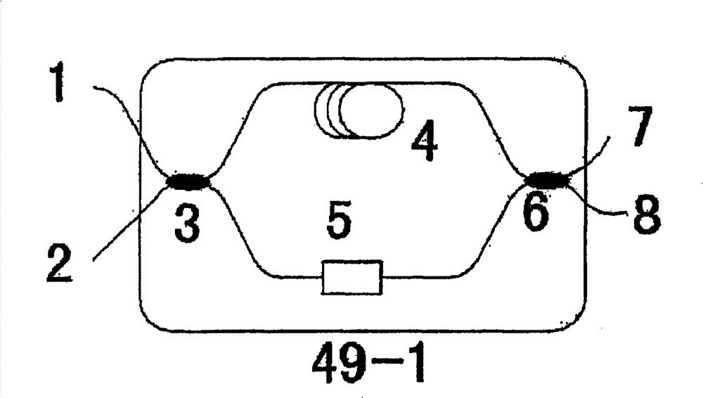
[0023] The first composition structure of the polarization control encoder in the quantum key distribution system of the present invention is as follows: figure 1 As shown: it consists of two 2×2 3dB polarization-maintaining beam splitters 3, 6, a polarization-maintaining phase modulator 5 and a polarization-maintaining delay line 4, which together form a polarization-maintaining Mach-Zehnder interferometer. One of the two ports 1 and 2 on one side of the 3dB polarization maintaining beam splitter 3 is used as the input end of the polarization control encoder, and one of the two ports 7 and 8 on the other side of the 3dB polarization maintaining beam splitter 6 is used as the output end , the polarization-maintaining phase modulator 5 and the polarization-maintaining delay line 4 (arbitrary order) are inserted into any arm of the above-mentioned Mach-Zehnder interferometer together, or both are respectively inserted into two arms of the above-mentioned Mach-Zehnder interferomet...

Embodiment 2

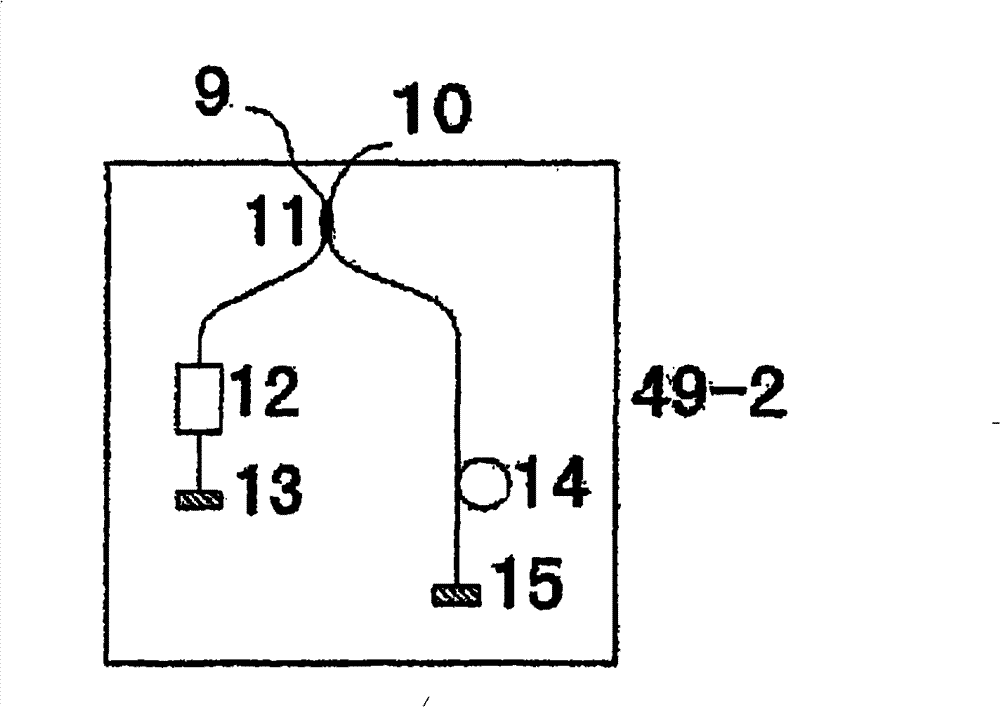
[0025] The second composition structure of the polarization control encoder in the quantum key distribution system of the present invention is as follows: figure 2As shown: it consists of a 2×2 3dB polarization maintaining beam splitter 11, two mirrors 13 and 15, a polarization maintaining phase modulator 12 and a polarization maintaining delay line 14. Wherein the two ports 9 and 10 on one side of the 3dB polarization maintaining beam splitter 11 can be used as the input and output ends of the polarization control encoder, and one of the two ports on the other side of the 3dB polarization maintaining beam splitter 11 is connected to the polarization maintaining The phase modulator 12, the reflector 13, and the other port on the same side are sequentially connected to the polarization maintaining delay line 14 and the reflector 15. A structure with a slight change but the same function is to connect the polarization maintaining delay line 14 and the polarization maintaining ph...

Embodiment 3

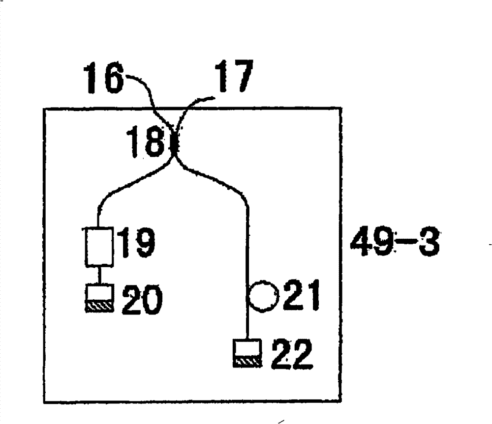
[0027] The third composition structure of the polarization control encoder in the quantum key distribution system of the present invention is as follows: image 3 As shown: it consists of a 2×2 3dB beam splitter 18, two 90-degree rotating Faraday mirrors 20 and 22, a phase modulator 19 and a delay line 21. Wherein the two ports 16 and 17 on one side of the 3dB beam splitter 18 are respectively used as the input and output ends of the polarization control encoder, and one of the two ports on the other side of the 3dB beam splitter 18 is connected to the phase modulator 19, 90 degrees in turn The Faraday reflector 20 is rotated, and the other port on the same side is sequentially connected to the delay line 21 and the 90-degree rotated Faraday reflector 22 . When working, the light pulse enters the beam splitter 18 through the port 16 of the beam splitter 18 and is divided into two paths, one path is delayed by a delay line 21, reflected back by a 90-degree rotating Faraday mirr...


PUM


Abstract

The invention relates to a polarization controlling encoding method, an encoder and a quantum key dispatching system. The invention is characterized in that the interior of the encoder adopts a polarization-maintaining light path or a ninety-degree Faraday rotation reflector reflection to cause output optical pulse polarization state to be the same; the optical pulse output by the sending terminal of the quantum key dispatching system taking the polarization controlling encoder as the core is passed to the receiving terminal thereof by a quantum channel in a uni-directional way; according to the superposition interference results of the optical pulse and distributorship agreement of the quantum key, the quantum key dispatching is realized. The polarization controlling encoder causes the whole system (comprising a sending set, a reception unit and the quantum channel) to have the interference free capability. The outlet of the sending set and the inlet of the receiving set of the system are added with a reversal photon separation detection unit, thus preventing the invasion of the modulation information and carrying the photon to get off the reception unit of Trojan photon. The quantum key dispatching system can realize unconditional secure assignment of the key.

Description

technical field [0001] The invention belongs to the technical field of optical transmission secure communication, in particular to an encoding method and device in quantum key distribution. Background technique [0002] Early quantum key distribution was encoded with photon polarization, which is suitable for free space communication but not for optical fiber communication system. Because the symmetry of ordinary optical fibers is not very good, and the interference in the transmission path is manifested as the influence on the polarization state of light, it cannot maintain the polarization state of light propagating in it, and polarization coding is not suitable for use in optical fibers. U.S. Patent No. 5,307,410 discloses a phase-encoded quantum key distribution scheme based on a pair of unequal-arm Mach-Zehnder (Mach-Zehnder) interferometers. Different arms of the special interferometer, because the interference received by different arms cannot be completely consisten...

Claims


Application Information

Patent Timeline
Patent Type & Authority Patents(China)
IPC IPC(8): G02B6/27H04L9/08H04B10/18H04B10/20H04B10/85
Inventor 韩正甫朱冰莫小范郭光灿
Owner ANHUI QASKY QUANTUM SCI & TECH CO LTD
Why Eureka
Try Eureka