Computer vision precision measurement based multi-projection visual automatic geometric correction and splicing method

A computer vision, geometric correction technology, applied in the direction of TV, color TV, color TV components, etc., to achieve the effect of improving work efficiency and quality

Active Publication Date: 2009-11-04
WISESOFT CO LTD
View PDF1 Cites 26 Cited by
  • Summary
  • Abstract
  • Description
  • Claims
  • Application Information

AI Technical Summary

Problems solved by technology

[0007] The purpose of the present invention is to address the deficiencies in the geometric correction of the multi-projection view of the existing curved display wall, and propose a method for au

Method used


Image

  • Computer vision precision measurement based multi-projection visual automatic geometric correction and splicing method
  • Computer vision precision measurement based multi-projection visual automatic geometric correction and splicing method
  • Computer vision precision measurement based multi-projection visual automatic geometric correction and splicing method

Examples


Embodiment Construction

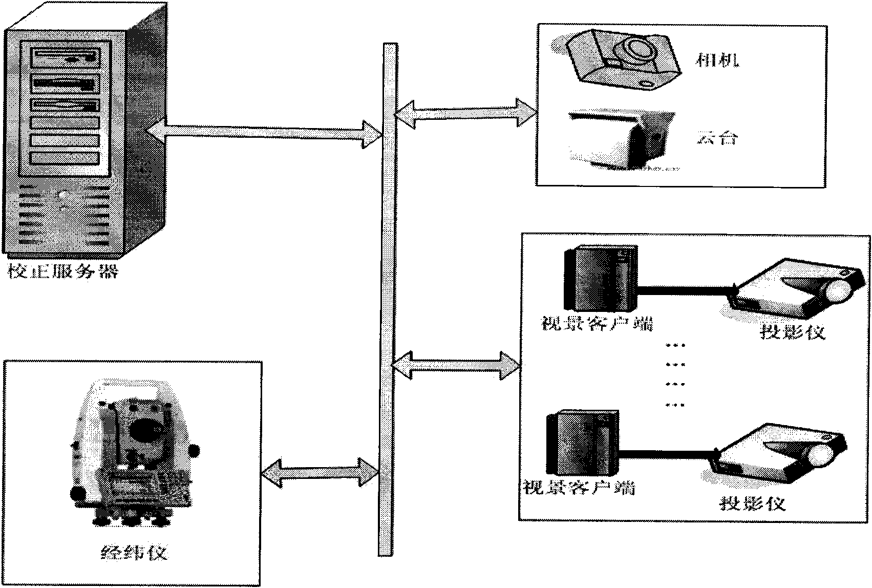
[0028] The hardware structure of multi-projection image geometric correction and stitching system can be found in figure 1. The whole system is composed of a calibration server, a computer-controlled theodolite, a computer-controlled digital camera, and a camera-mounted pan / tilt. The computer-controlled theodolite sends latitude and longitude control commands to the theodolite through the computer, and the rotation mechanism of the theodolite can drive the laser pointer on the theodolite to rotate the laser point to the specified spatial latitude and longitude position. Using the pixel-level mapping relationship between the image projected by the projector on the display wall and the computer frame buffer image, the latitude and longitude projected imaging grid is inversely mapped to the computer source image coordinate space grid.

[0029] When the computer sends the angle measurement command to the theodolite, the theodolite should be able to rotate to the specified latitud...


PUM


Abstract

The invention relates to a computer vision precision measurement based multi-projection visual automatic geometric correction and splicing method, and belongs to the large visual field ultrahigh resolution image display and processing. A theodolite with a laser head is automatically controlled by the computer and is a device for measuring the longitude and latitude distribution situation of a display wall based on human viewpoints; a digital camera is used to shoot and record the position of a laser point; the computer identifies the position of the theodolite laser point on the digital camera image and works out the coordinate position of the laser point on a projection source image through inversion; and the longitude and latitude of a coordinate point on the projection source image is the current measuring angle of the theodolite. Image grids corresponding to the longitude and latitude grids are established in the two-dimensional coordinate space of the projection source image; an image to be displayed is divided according to the longitude and latitude grids data distribution or the three-dimensional visual model scene data is colored according to the longitude and latitude grids; and each image is mapped to the image grids so as to generate a seamlessly spliced multi-projection image without visual geometric distortion. The method effectively solves the problems of the prior art, and has an automatically executed correction and splicing process, and high efficiency and quality.

Description

technical field [0001] The invention relates to image display processing, in particular to an image correction and splicing method for a large-scale multi-channel projection display system. Background technique [0002] With the rapid development of industry, commerce, entertainment and scientific visualization, the demand for high-resolution and large-field-of-view display systems is becoming stronger and stronger. The current mainstream display devices usually only have a resolution of several million pixels. Due to technical limitations, it is impossible to achieve super large field of view and high resolution to meet people's needs for display systems. Using a single device cannot meet the current needs, but a large-screen display system that uses multiple projectors seamlessly spliced ​​can better solve this problem. The high-resolution multi-projection display system uses multiple projectors to form a large-screen system, which has larger display size, wider field of...

Claims


Application Information

Patent Timeline
IPC IPC(8): H04N5/74G03B21/00
Inventor 王邦平李晓峰张军易成
Owner WISESOFT CO LTD
Why Eureka
Try Eureka