Zero-point positioning system, method and device for joint of robot

A robot joint and zero point positioning technology, applied in the field of robots, can solve problems such as complex circuits, and achieve the effect of simplifying the system structure and reducing costs

Inactive Publication Date: 2009-11-11
BEIJING HUAKAIHUI INFORMATION TECH
View PDF0 Cites 36 Cited by
  • Summary
  • Abstract
  • Description
  • Claims
  • Application Information

AI Technical Summary

Problems solved by technology

After analyzing the second prior art, the inventor found that the second prior art has at least the following disadvantages: at least two switches need to be set at the extreme positions of the range of motion of the joints to prevent the robot from randomly moving in a certain direction when it is powered on. The z

Method used


Image

  • Zero-point positioning system, method and device for joint of robot
  • Zero-point positioning system, method and device for joint of robot
  • Zero-point positioning system, method and device for joint of robot

Examples


Embodiment 1

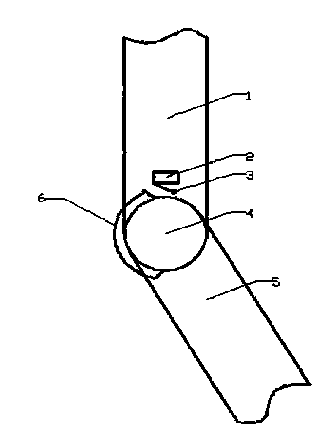
[0045] An embodiment of the present invention provides a robot joint zero point positioning system, figure 1 It is a schematic diagram (front view) of the mechanical structure of the robot joint equipped with the zero point positioning system. Wherein, the robot rod A1 and the robot rod B5 are respectively connected with the robot joint 4 and can rotate clockwise or counterclockwise around the robot joint 4 . In the embodiment of the present invention, in order to perform zero-point positioning on the robot joints, a travel switch 2 is fixed on the joint side of the robot rod A1. At one end of limit switch 2. The zero stop 6 of the robot rod B5 is made of a thin sheet bent into an arc shape, and is fixed on the joint side of the robot rod B5, and is used to touch or stay away from the travel switch of the travel switch 102 when the rod B105 rotates. link. The zero stopper 6 can be made of thin sheets such as metal sheets and plastic sheets, and its center of circle can be l...

Embodiment 2

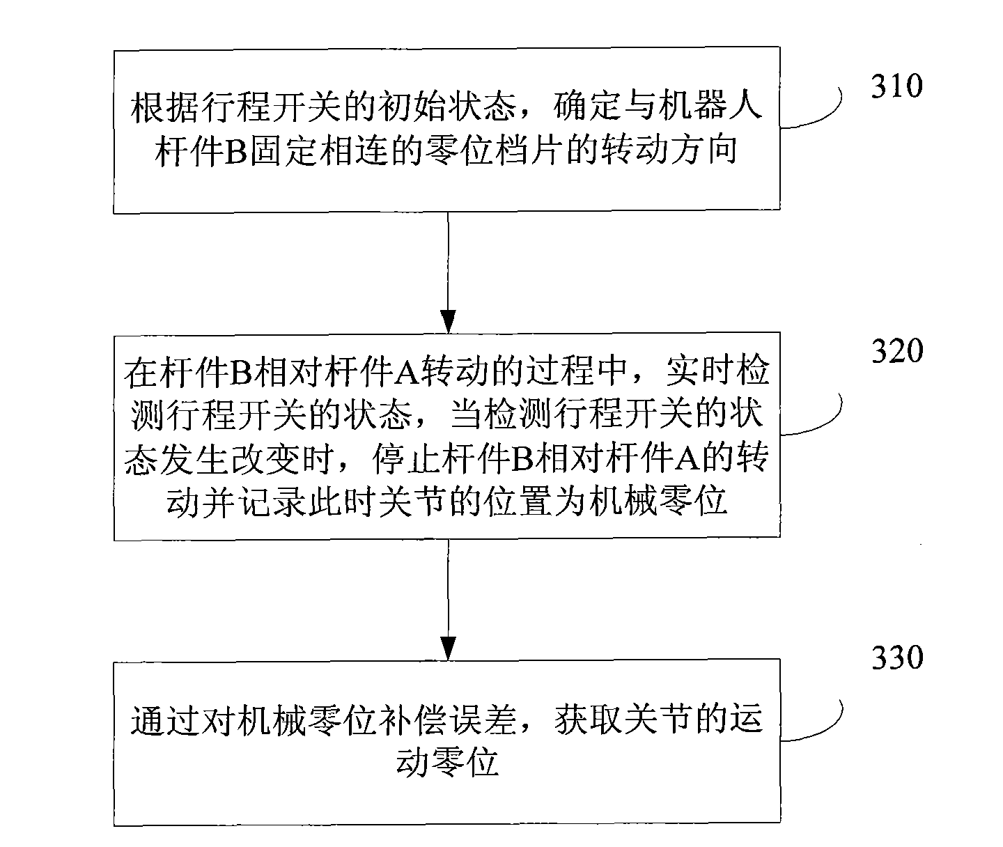
[0059] An embodiment of the present invention provides a robot joint zero point positioning method, such as image 3 shown, including the following steps:

[0060] 310: According to the initial state of the limit switch, determine the rotation direction of the zero stop fixedly connected with the robot bar B, wherein the limit switch is fixedly arranged on the joint side of the robot bar A.

[0061] see figure 1 , the rod A1 is connected with the rod B5 through the joint 4, and can rotate clockwise or counterclockwise around the joint 4 of the robot. The zero stopper 6 is a sheet bent into an arc shape, and is fixed on the joint side of the robot rod B5. The zero stopper 6 can be made of sheet materials such as metal sheets and plastic sheets, and its center of circle is located at the joint 4 vertical to the central axis of the paper. In this embodiment, the central angle of the zero stopper 6 may be about 130 degrees.

[0062] Further, in step 310, according to the initi...

Embodiment 3

[0075] An embodiment of the present invention provides a robot joint zero point positioning device, see Figure 4 ,include:

[0076] The judging module 401 is used to determine the rotation direction of the zero stop fixedly connected to the robot rod B according to the initial state of the travel switch, wherein the travel switch is fixed on the joint side of the robot rod A.

[0077] Judgment module 401 includes:

[0078] The judging unit is used to determine the initial state of the travel switch, and the travel switch is fixed on the joint side of the rod A of the robot. For a specific method of determining the initial state of the travel switch, refer to the descriptions in Embodiments 1 and 2.

[0079] The execution unit is used to rotate the zero position plate fixedly connected with the robot bar B to the direction away from the travel switch connecting rod of the travel switch if the travel switch is initially in the closed state; if the travel switch is initially i...


PUM


Abstract

The invention discloses a zero-point positioning system for joint of robot and a method and a device thereof, and belongs to the technical field of robot. The system comprises a travel switch, a rotation direction detecting device, a microcontroller and a zero-position stopping piece, wherein the travel switch is fixedly arranged at the joint side of a robot rod piece A; the rotation direction detecting device is connected with an electric motor; the microcontroller is connected with the travel switch and simultaneously is driven to be connected with the electric motor and the rotation direction detecting device; the zero-position stopping piece is formed by bending a thin section into a circular arc shape and is fixedly arranged at the joint side of a robot rod piece B; and the rod piece A and the rod piece B are connected with each other by a joint. The method includes: determining the rotation direction of the zero-position stopping piece according to the initial state of the travel switch; and stopping the rotation and recording the position of the joint at the moment as mechanical zero position when the state of the travel switch is changed. The device comprises a judge module and a mechanical zero-position acquisition module. The invention simplifies the system structure and reduces the cost.

Description

technical field [0001] The invention relates to the technical field of robots, in particular to a robot joint zero point positioning system, method and device. Background technique [0002] A robot generally realizes various motion functions by combining multiple joints. Obtaining the zero position of each joint when the robot is initially powered on is a prerequisite for the robot to perform various motions. The existing robot joint zero point positioning device usually adopts the following technical solutions: [0003] The prior art one adopts an absolute code disc. The absolute code disc is generally set at the joint of the robot, and the absolute position of the joint can be obtained by reading the output data information of the absolute code disc when the power is turned on. This solution is the most simple and direct, but after analyzing the existing technology, the inventor found that: the absolute code disk is generally large in size, complicated in connection, exp...

Claims


Application Information

Patent Timeline
IPC IPC(8): B25J19/00B25J17/00
Inventor 段星光黄强李建玺
Owner BEIJING HUAKAIHUI INFORMATION TECH
Why Eureka
Try Eureka