Steel-concrete combined continuous rigid frame bridge construction method for cantilever jointing steel box section

A construction method and technology for rigid frame bridges, applied in the direction of erecting/assembling bridges, bridges, bridge construction, etc., can solve the problem of high sensitivity of continuous rigid frame bridge materials and construction quality, affecting the normal service performance of bridges, structural durability, technical Require high-level issues, achieve the effect of reducing construction equipment requirements, avoiding concrete cracking under tension, and simple equipment

Inactive Publication Date: 2009-11-11
CHONGQING JIAOTONG UNIVERSITY
View PDF0 Cites 16 Cited by
  • Summary
  • Abstract
  • Description
  • Claims
  • Application Information

AI Technical Summary

Problems solved by technology

However, its process is complicated, the technical requirements are high, and the construction period is long.
The concrete material used in the bridge and its construction quality determine its shrinkage and creep performance, the prestress tension control determines the effectiveness of the prestress in the beam, and the quality of the vertical joints between the main beam sections affects the actual working state of t

Method used


Image

  • Steel-concrete combined continuous rigid frame bridge construction method for cantilever jointing steel box section
  • Steel-concrete combined continuous rigid frame bridge construction method for cantilever jointing steel box section
  • Steel-concrete combined continuous rigid frame bridge construction method for cantilever jointing steel box section

Examples


Example Embodiment

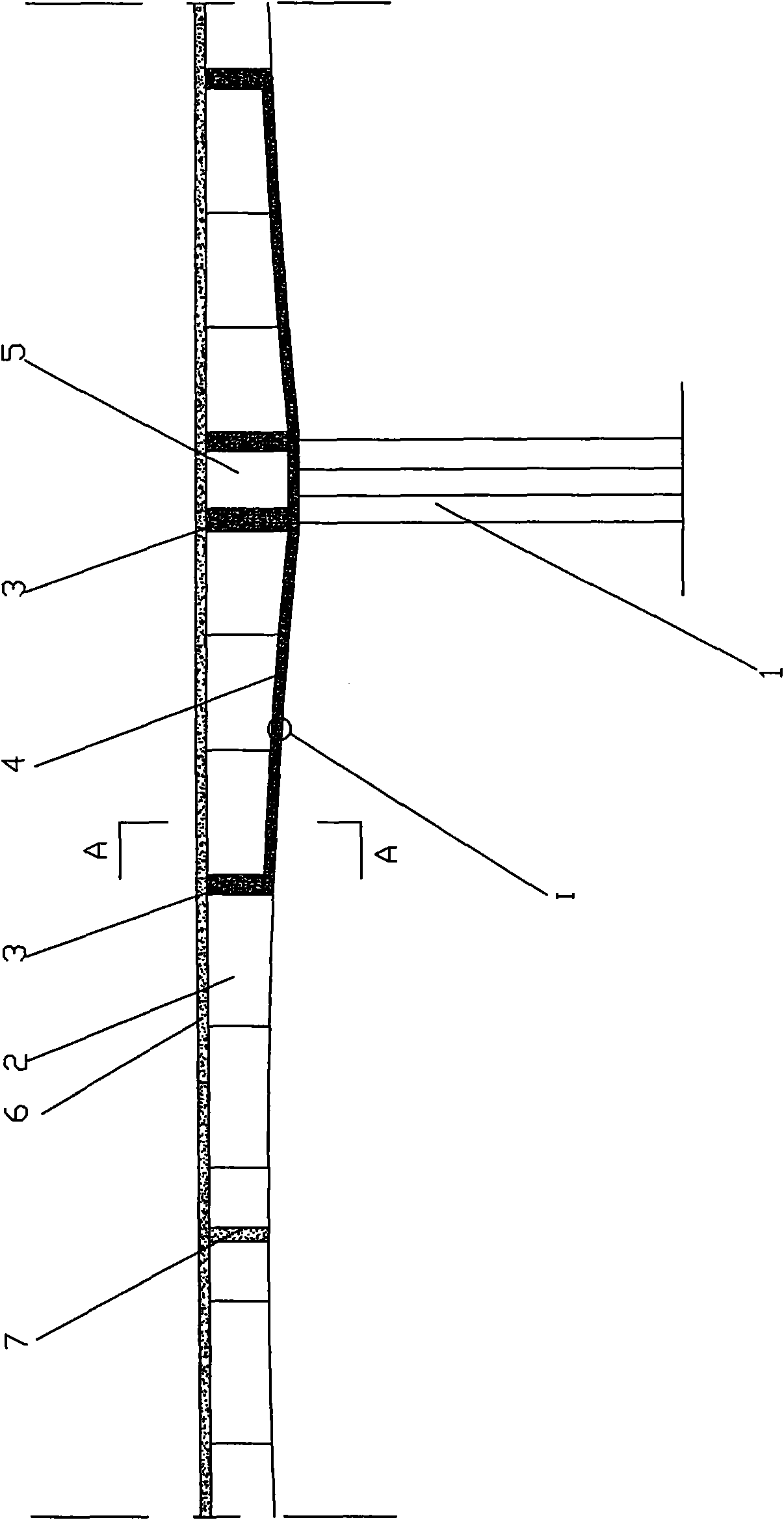
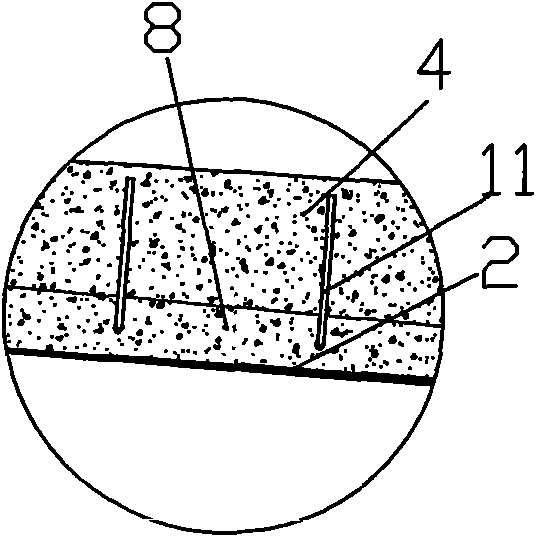
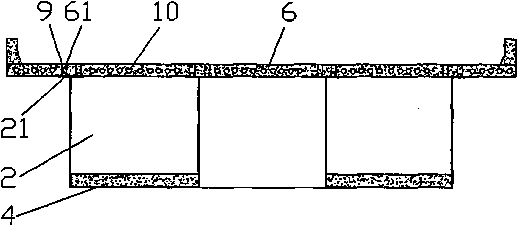
[0024] figure 1 This is a schematic diagram of the structure after construction of this method, figure 2 for figure 1 Enlarged view at I, image 3 for figure 1 Take the A-A section view, Figure 4 This is an enlarged view of the partial longitudinal section of the concrete bridge road slab under the negative bending moment of the present invention, as shown in the figure: The construction method of the steel-concrete combined continuous rigid frame bridge with cantilever assembled steel box segments of the present invention includes the following steps:

[0025] a. Complete the construction of pier 1, install the pier top steel box girder section 5 on the top of the pier 1, and pour the pier top diaphragm 3 to increase the strength;

[0026] b. The prefabricated steel box girder sections 2 are respectively cantilevered to both sides of the bridge pier 1; and the two adjacent piers 1 are cantilevered to the mid-span area respectively. The cross-sectional shape of the steel box ...


PUM


Abstract

The invention discloses a steel-concrete combined continuous rigid frame bridge construction method for cantilever jointing steel box section, which comprises the steps of: adopting the cantilever jointing steel box section and casting the concrete of a bottom board inside the board timely, continuing to carry out the cantilever jointing steel box section to side and middle span closure, mounting the guidance tape of a concrete bridge in sections and applying a longitudinal inherent stress, and then combining the cantilever jointing steel box section with a girder to become an integrity. Compared with the same-span diameter normal inherent stress concrete continuous rigid frame bridge, the method can significantly simplify the construction technique, reduce the dead weight of the main girder by about 40 percent, correspondingly reduce the quantities of the lower structure and the basic engineering, correspondingly improve the span capacity, and shorten the working period of the main girder by more than 30 percent. The method leads each part of the continuous rigid frame bridge to be stressed definitely and has stable and reliable structural performances for a long period, fully exerts the strength advantages of steel and concrete, and avoids the structural hidden dangers of the traditional continuous rigid frame bridge with over-large deflection for a long period of time and the like caused by the less reliable performance of a curve prestressing tendon, cracks of the concrete due to pulling, as well as shrinkage and creep of the concrete.

Description

Technical field [0001] The invention relates to a construction method of a bridge, in particular to a construction method of a steel-concrete combined continuous rigid frame bridge in which steel box segments are cantilevered together. Background technique [0002] The continuous rigid frame bridge has a simple configuration and has good adaptability to the V-shaped valley. Its main beam is a bending member, which is consolidated by piers and beams to avoid structural cracks. It has strong integrity and good performance. The bridge has better performance. Strong ductility and earthquake resistance. Continuous rigid frame bridges are generally constructed by segmented cantilever casting or cantilever assembly methods, which have low requirements on the construction site. After years of practice, the cantilever construction method has mature technology and good safety. But its process is complicated, technical requirements are high, and construction period is long. The concrete mat...

Claims


Application Information

Patent Timeline
IPC IPC(8): E01D21/10
Inventor 周志祥
Owner CHONGQING JIAOTONG UNIVERSITY
Why Eureka
Try Eureka