
A treatment method for engine failure

A treatment method and engine technology, which is applied in the direction of engine components, engine control, machine/engine, etc., can solve the problems of engine safety hazards, no emergency treatment, and reduced car safety, so as to ensure safe driving

Inactive Publication Date: 2011-12-14
CHINA VAGON AUTOMOTIVES HLDG CO LTD
View PDF0 Cites 0 Cited by
  • Summary
  • Abstract
  • Description
  • Claims
  • Application Information

AI Technical Summary

Problems solved by technology

The existing technology only diagnoses the camshaft, but there is no relevant emergency treatment. Therefore, when the camshaft fails, if it cannot be dealt with in time, there will be a safety hazard in the engine, which greatly reduces the safety of the car.

Method used


Image

  • A treatment method for engine failure
  • A treatment method for engine failure
  • A treatment method for engine failure

Examples


Embodiment Construction

[0015] The specific implementation manners of the present invention will be further described in detail below in conjunction with the accompanying drawings and embodiments. The following examples are used to illustrate the present invention, but are not intended to limit the scope of the present invention.

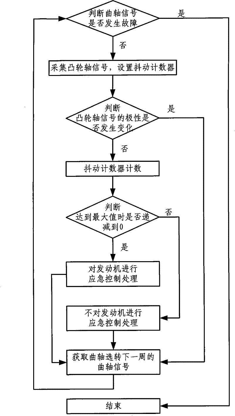
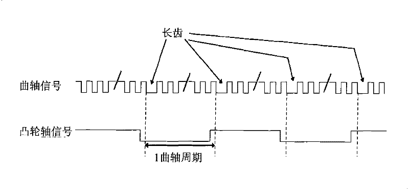
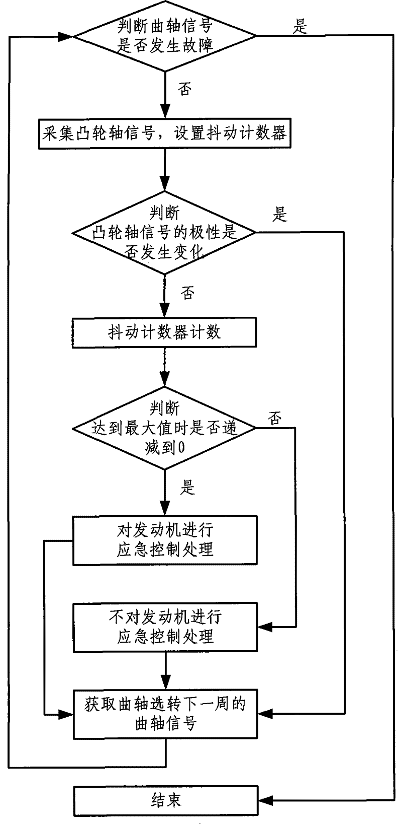
[0016] figure 1 It is a flowchart of a method for processing camshaft signals by an ECU according to an embodiment of the present invention. figure 2 The exact camshaft signal and crankshaft signal diagrams involved in this example are shown, figure 2 The waveform diagram above shows the crankshaft signal, and the arrow marks the pulse of the long tooth signal; figure 2 The waveform diagram below shows the camshaft signal, and the part inside the dotted line shows the camshaft signal in one cycle. It can be seen that the normal camshaft signal must change its polarity once in one cycle. combine figure 2 It can be seen that the polarity of the crankshaft signal and ...


PUM


Abstract

The invention discloses a processing method for an engine failure, which comprises the following steps: obtaining a camshaft signal of one rotation of the crankshaft; judging whether the polarity of the camshaft signal changes, and when the polarity of the camshaft signal does not occur When it is changed, emergency control processing is performed on the engine to make the engine run normally. The ECU in the present invention collects the signal of the camshaft position sensor, and then diagnoses the camshaft signal to determine whether the signal has a fault condition of multiple teeth or missing teeth. Then emergency control of the engine with camshaft failure occurs. This diagnostic technology is executed when the engine is running, and the camshaft signal is constantly monitored to ensure the safe driving of the vehicle.

Description

technical field [0001] The invention relates to the field of engine control, in particular to a processing method after an engine camshaft signal fails. Background technique [0002] There are clear regulations in the quality requirements of today's automobiles, and the ECU (Electronic Control Unit, Electronic Control Unit) of the automobile must have the function of diagnosing each running part of the automobile. These diagnostic functions are to assist the ECU to make emergency driving control actions when there is an engine failure during the driving of the car, so as to protect the driving safety of the driver and the vehicle. The diagnostic method mainly includes the following diagnostic objects: camshaft diagnosis, crankshaft diagnosis, intake air temperature sensor diagnosis, knock sensor diagnosis, oxygen sensor diagnosis, coolant and cooling fan control relay diagnosis, air conditioning control relay diagnosis wait. The existing technology only diagnoses the camsh...

Claims


Application Information

Patent Timeline
Patent Type & Authority Patents(China)
IPC IPC(8): F02D41/14F01L1/344
Inventor 李朝晖张步亮吕国伟周杰雄
Owner CHINA VAGON AUTOMOTIVES HLDG CO LTD
Learn More