Solar energy photo-thermal high-temperature utilization system

A solar energy and photothermal technology, applied in the field of solar photothermal high temperature utilization system, can solve the problems of high cost, high price of tracking device related components, unstable performance, etc. Simple and reasonable effect

Inactive Publication Date: 2009-11-11
李捷
View PDF0 Cites 3 Cited by
  • Summary
  • Abstract
  • Description
  • Claims
  • Application Information

AI Technical Summary

Problems solved by technology

Before 1990, reflective surface tracking heat collection was not popular due to technical and price problems such as reflective surface materials and tracking brackets; from 1990 to 2008, the United States, Israel and China had developed the method of tracking fixed heat collector tubes on reflective surfaces to manufacture large-area light Thermal devices are used in industrial fields such as power generation, but the effect is not ideal due to the displacement and width of the spot
[0004] In recent years, the country has turned to the research on the tracking and focusing method of the reflective surface. The "spring wheel automatic tracking machine" of Shaanxi Normal University strives to use the "spring wheel" to drive the bracket to automatically track. Since the "spring wheel" must be manually pushed to store energy every day, it has not been able to Popularity; the "quasi-tracking" in Dezhou, Sh

Method used


Image

  • Solar energy photo-thermal high-temperature utilization system
  • Solar energy photo-thermal high-temperature utilization system
  • Solar energy photo-thermal high-temperature utilization system

Examples


Embodiment Construction

[0017] Below in conjunction with accompanying drawing and embodiment the present invention will be further described:

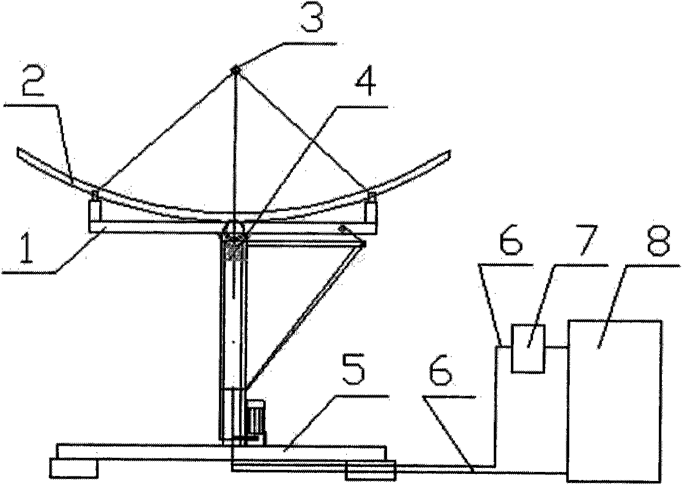
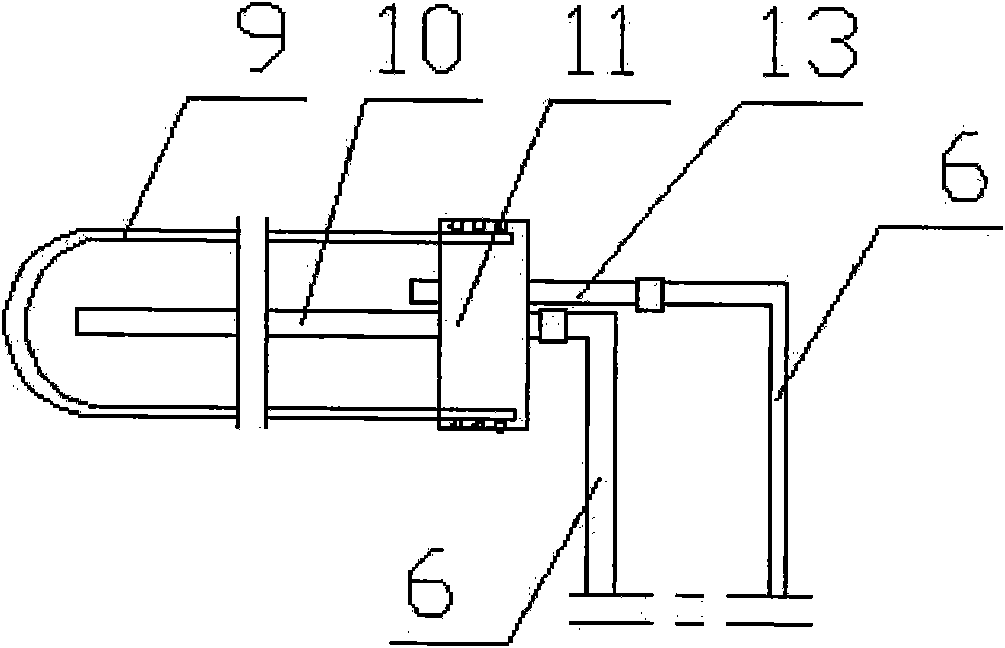
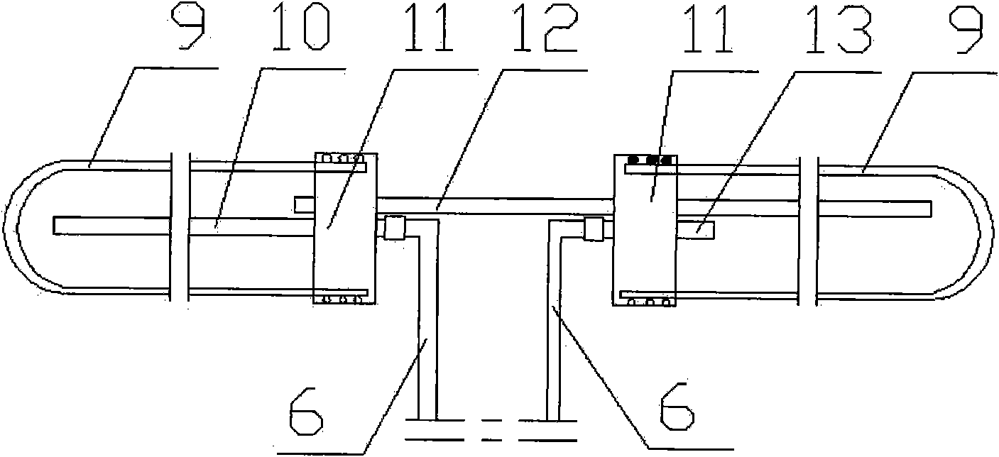
[0018] With reference to accompanying drawing, the present invention comprises main engine 1, oil pump 7 and heat exchanger 8, and described main engine 1 comprises main engine 1, oil pump 7 and heat exchanger 8 and heat medium thereof by concentrating device 2, heat collector 3, tracking device , the main engine 1 is composed of a concentrating device 2, a heat collector 3, a tracking device 4 and a base 5, the heat collector 3, an oil pump 7 and a heat exchanger 8 are connected by an oil pipe 6, and the heat collector 3 is connected by The bracket is installed and fixed on the focusing point of the concentrating device 2, and the heat exchanger 8 is connected to at least one main engine 1; the heat collector 3 is composed of a heat collecting pipe 9 and its seal 11, an oil inlet pipe 10 and an oil return pipe 13 ; The heat collecting tube 9 adopts a U-shape...


PUM


Abstract

The invention discloses a solar energy photo-thermal high-temperature utilization system, which comprises a mainframe, an oil pump, a heat exchanger and a heating medium of the heat exchanger, wherein the mainframe consists of a beam condensing unit, a heat collector, a tracker and a pedestal; the heat collector, the oil pump and the heat exchanger are connected with each other through an oil pipe; the heat collector is fixed on a focus point of the beam condensing unit through a support; the heat exchanger is at least connected with one mainframe; the heat collector consists of a heat collecting pipe, a sealing element of the heat collecting pipe, an oil inlet pipe and an oil return pipe; the heat collecting pipe adopts a U-shaped high silicon boron double-layered vacuum glass heat pipe, and the opening end of the heat collecting pipe is sealed by the sealing element; after the oil inlet pipe passes through the sealing element and enters the heat collecting pipe, the end part of the oil inlet pipe is close to the remote end of the heat collecting pipe; after the oil return pipe passes through the sealing element and enters the heat collecting pipe, the end part of the oil return pipe is close to the tail end of the heat collecting pipe; the oil inlet pipe is connected with an outlet of the oil pump through an oil pipe; and the oil return pipe is connected with the heat exchanger through an oil pipe. The solar energy photo-thermal high-temperature utilization system has a simple and reasonable structure, high automatic sunlight tracking precision, high sunlight utilization efficiency, low manufacturing cost and operation cost, and is clean and environment-friendly.

Description

technical field [0001] The invention relates to a solar energy receiving and converting device, in particular to a solar light-heat high-temperature utilization system for solar light-heat conversion and utilization. Background technique [0002] Solar energy generally refers to the radiant energy of sunlight. The atomic nuclear reaction that fuses "hydrogen" into "helium" in the sun continuously releases huge energy and continuously radiates energy to the outer space. This energy is solar energy. This nuclear fusion reaction inside the sun can last for billions to tens of billions of years. The radiation power emitted by the sun to space is 3.8x10^23kW, of which 1 / 2 billion reaches the earth's atmosphere. 30% of the solar energy reaching the earth's atmosphere is reflected by the atmosphere, 23% is absorbed by the atmosphere, and the rest reaches the surface of the earth. The heat released by tons of coal. In a broad sense, solar energy is the source of many energies on...

Claims


Application Information

Patent Timeline
IPC IPC(8): F24J2/30F24J2/46F24J2/38F24S10/30F24S50/20
CPCY02E10/44Y02E10/47
Inventor 李捷
Owner 李捷
Why Eureka
Try Eureka