Eureka AIR delivers breakthrough ideas for toughest innovation challenges, trusted by R&D personnel around the world.

Touch-control signal transmission circuit and display using same

A technology for transmitting circuits and touch signals, which is applied to instruments, electrical components, electronic switches, etc., and can solve problems such as increased reflectivity, increased weight, and decreased transmittance

Inactive Publication Date: 2009-11-11
CHI HSIN ELECTRONICS CORP
View PDF0 Cites 14 Cited by
  • Summary
  • Abstract
  • Description
  • Claims
  • Application Information

AI Technical Summary

Problems solved by technology

Known touch sensing principles include resistive, capacitive, and electromagnetic induction, etc. Although the current touch sensing devices are mostly resistive, the control is limited because the resistive type cannot perform multi-touch, and the resistive structure Touch pressure sensing is required, which can easily cause specific parts of the panel to withstand repeated stress for a long time and be damaged. Therefore, capacitive touch sensing devices with multi-touch functions and without excessive stress on the panel are gradually becoming popular in the market. attention
[0003] Even though the capacitive touch sensing device has a market advantage, it is still combined with the display in an attached manner, which will increase the thickness and weight of the overall panel, and may also damage the optical display effect, such as decreased transmittance or The reflectivity rises. For the increasingly refined design of electronic products, the above-mentioned deficiencies seem to be improved.

Method used


Image

  • Touch-control signal transmission circuit and display using same
  • Touch-control signal transmission circuit and display using same
  • Touch-control signal transmission circuit and display using same

Examples


Embodiment Construction

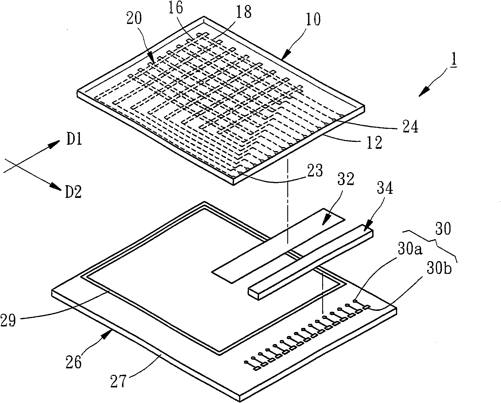
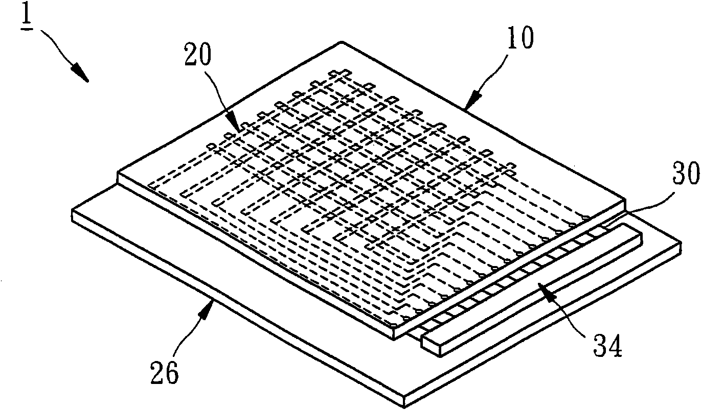
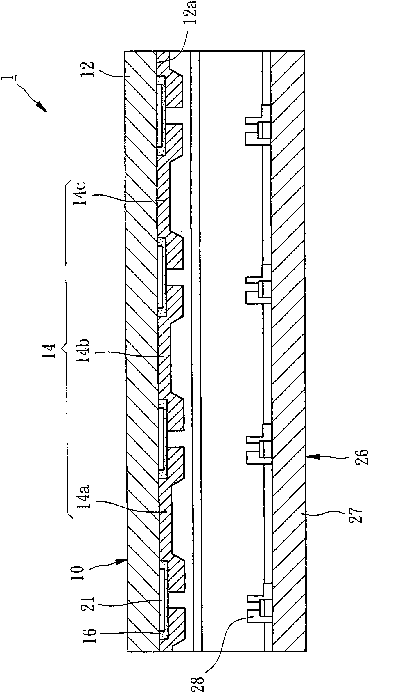
[0029] Figure 1 to Figure 3 It is a schematic diagram of a liquid crystal display 1 using a touch signal transmission circuit of the invention according to the first preferred embodiment of the invention. The liquid crystal display 1 includes an upper substrate 10, a touch signal transmission circuit 20, a lower substrate 26, and a conductive layer. 32 and a touch IC 34, the following description does not describe the manufacturing process, but only describes the features and relative positions of each component of the final structure:

[0030] The upper substrate 10 of this embodiment is a color filter substrate including a transparent body 12 and a color filter layer 14, wherein the color filter layer 14 is formed on the inner surface 12a of the transparent body 12, and its composition includes a A black matrix (BM) and a plurality of red, green, and blue filter units 14a, 14b, 14c; the aforementioned black matrix is ​​made of black resin material and includes a plurality of fi...


PUM


Abstract

The invention relates to a touch-control signal transmission circuit and a display using same. A plurality of first electrodes and second electrodes, which are mutually electrically insulated and alternately arranged along a first direction and a second direction respectively, are arranged on the inner surface of an upper base plate which is used for forming a liquid crystal display, and a touch-control induction zone is formed by the interlaced range of the first electrodes and the second electrodes. When fingers touch the surface of the upper base plate and touch and control in the touch-control induction zone, the display can be controlled or started, and the first electrodes and the second electrodes, which are used for touch-control induction, are arranged on the inner surface of the upper base plate, so the integral thickness and the weight of the display are reduced.

Description

Technical field [0001] The present invention is related to the control structure of the liquid crystal display, and more specifically refers to a touch signal transmission circuit and a display using the touch signal transmission circuit. Background technique [0002] The touch sensor device detects the position of a finger or an object touching the panel, and then transmits a signal to achieve the purpose of control or activation. It is the simplest and most user-friendly input method at this stage, so it is often used in many electronic products. Known touch sensing principles include resistive, capacitive, electromagnetic induction, etc. Although most of the current touch sensing devices are resistive, the resistive type cannot perform multi-touch, which limits the control and resistive structure. The need for force touch and pressure sensing is likely to cause damage to certain parts of the panel that are subjected to repeated stress for a long time. Therefore, capacitive tou...

Claims


Application Information

Patent Timeline
Patent Type & Authority Applications(China)
IPC IPC(8): G02F1/13G02F1/1335H03K17/96
Inventor 赖辉龙张政衍
Owner CHI HSIN ELECTRONICS CORP
Why Eureka
Eureka Blog
Learn More