
Light-emitting diode (LED) sensing and controlling system

A light-emitting diode and induction control technology, which is applied in the field of light-emitting diode induction control system, achieves the effects of cost saving, simple logic control, and high user satisfaction

Inactive Publication Date: 2009-11-11
FUJIAN STAR NET EVIDEO INFORMATION SYST CO LTD
View PDF0 Cites 2 Cited by
  • Summary
  • Abstract
  • Description
  • Claims
  • Application Information

AI Technical Summary

Problems solved by technology

But there is no application that can directly control logic through LED

Method used


Image

  • Light-emitting diode (LED) sensing and controlling system
  • Light-emitting diode (LED) sensing and controlling system
  • Light-emitting diode (LED) sensing and controlling system

Examples


Embodiment Construction

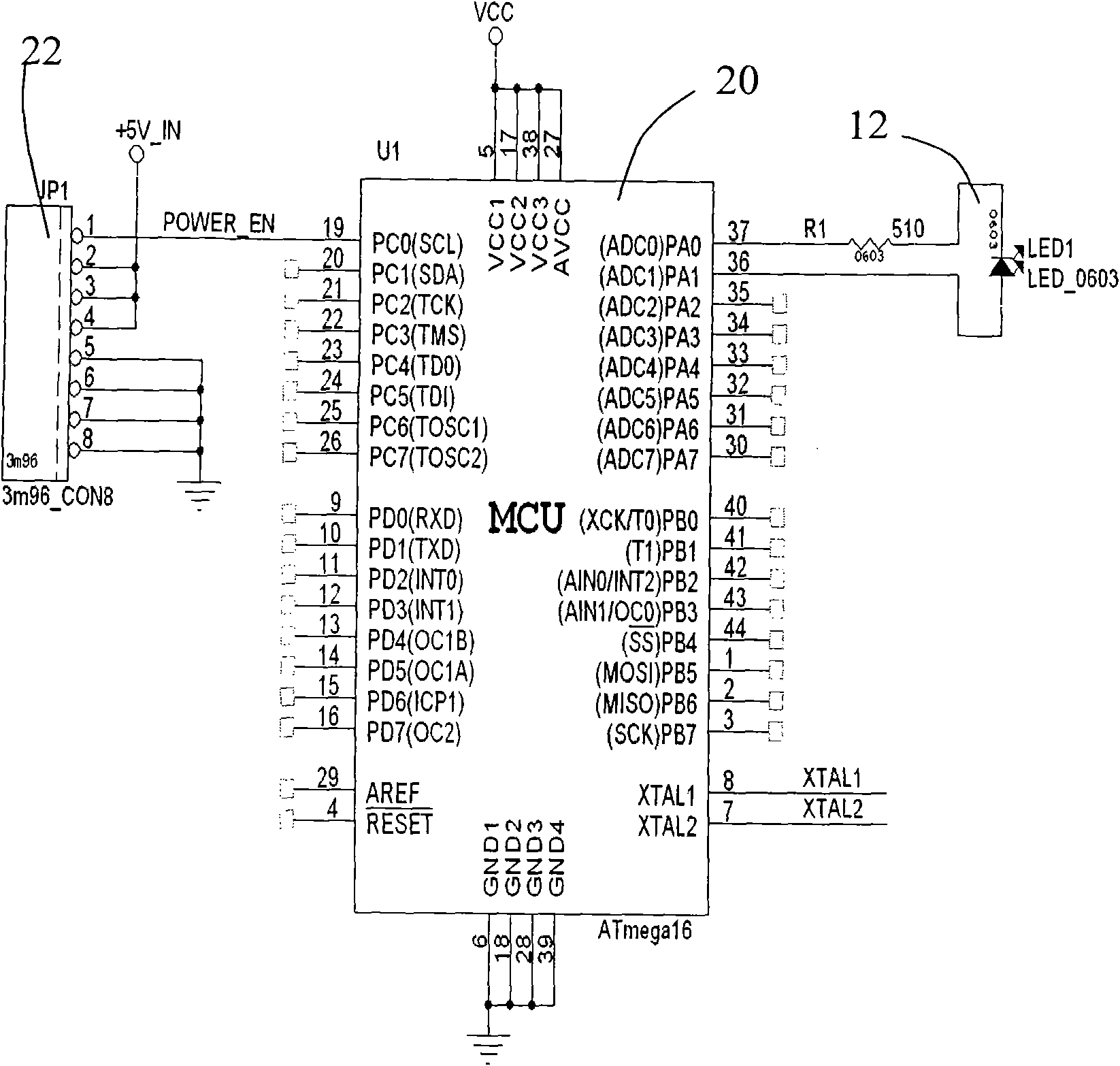
[0032] see figure 1 , the light-emitting diode sensing control system of the present invention includes a LED (light-emitting diode) module 10 , an MCU (micro-controller) 20 , and a controlled device 30 . The LED module 10 and the controlled device 30 are both controlled by the MCU 20 , and the LED module 10 is not only used as a light indicator element with an indication function, but also as a touch sensor element for controlling external logic states. The LED module 10 can be a light emitting diode, or a combination of multiple light emitting diodes, and the controlled device 30 can be a power control module, a volume control module, a time schedule control module, or a power adjustment device.

[0033] see figure 2 , is a block diagram of the connection relationship of the first embodiment of the light-emitting diode sensing control system of the present invention. At this time, the LED module 10 is used as an inductive power switch, and has the functions of touch receiv...


PUM


Abstract

The invention relates to a light-emitting diode (LED) sensing and controlling system which comprises an LED module, a microcontroller and controlled equipment, wherein both the LED module and the controlled equipment are controlled by the microcontroller to work; the LED module is used as a light indicator for indicating the state of the controlled equipment; the LED module is also used as a touchsensor; and after the microcontroller detects that the LED module is touched, the relative control logic judgment is executed, thereby the controlled equipment is controlled. The LED sensing and controlling system carries out logic processing by utilizing the characteristics of an LED through a series of processing so as to realize simple logic control, enables the LED to have both a control function and an indicating function and has the advantages of low price, cost saving, high user satisfaction degree, fashion and attractive appearance.

Description

【Technical field】 [0001] The invention relates to a light emitting diode application system, in particular to a light emitting diode induction control system. 【Background technique】 [0002] LED (Light Emitting Diode) devices are currently widely used indicating devices. The price is low, there are many varieties, and there are generally many colors. This technology is already a very mature technology. But there is no application that can directly control the logic through the LED. Many unexpected effects can be brought about through the alternative use of LEDs. 【Content of invention】 [0003] The technical problem to be solved by the present invention is to provide a light-emitting LED that utilizes the electrical characteristics of LEDs, taps its special functions, solves people's satisfaction with use, and satisfies the current customer's desire for convenience. Diode induction control system. [0004] Diodes have a number of special properties when reverse biased....

Claims


Application Information

Patent Timeline
IPC IPC(8): H05B37/02H03K17/94F21V23/00F21W111/00F21W131/403F21Y101/02F21Y115/10
CPCY02B20/42Y02B20/40
Inventor 陈风邱作霖
Owner FUJIAN STAR NET EVIDEO INFORMATION SYST CO LTD
Learn More