Video-monitored printing machine

A video sequence, machine technology, applied in the field of process in the machine, can solve the problem that there is no effective method for detecting and displaying the printing machine

Active Publication Date: 2009-11-18
HEIDELBERGER DRUCKMASCHINEN AG
View PDF3 Cites 12 Cited by
  • Summary
  • Abstract
  • Description
  • Claims
  • Application Information

AI Technical Summary

Problems solved by technology

The laid-open document DE 10 2004 015 333 A1 therefore relates to the construction of a monitoring system with cameras

Method used


Image

  • Video-monitored printing machine
  • Video-monitored printing machine
  • Video-monitored printing machine

Examples


Embodiment Construction

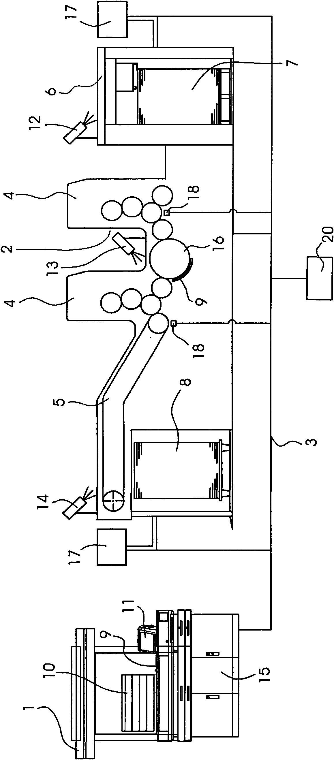
[0021] figure 1 A sheet printing press 2 with two printing units 4 is shown in . The printing press 2 is fed by a feeder 6 with printed sheets 9 , which are removed from a feeder stack 7 . The sheets 9 are transported from the feeder 6 to the printing unit 4 and printed with ink there. In the last printing unit 4 , the sheet 9 reaches the delivery 5 , where the sheet 9 is deposited on the delivery stack 8 . In the printing press 2 , the printed sheet 9 is transported from the feeder 6 to the delivery 5 by means of a cylinder 16 . The printing press 2 can be controlled by a control console 1 which has a control computer 15 . The control computer 15 is connected to the electric drive in the printing press 2 via a communication link 3 , which is designed as a network connection, for example a CAN bus connection or an Ethernet connection. Operating console 1 also has a touch screen 11 and a large screen 10 which are likewise connected to a control computer 15 . A graphical us...


PUM


Abstract

A method for displaying events in printing material processing machines (2), includes capturing the events with at least one camera (12, 13, 14) and storing the captured events on a computer (15). Sensors (18) for detecting machine states are provided in the printing material processing machine (2). Records of the events recorded by the camera (12, 13, 14) as a video sequence (19) are electronically marked in dependence on the detected machine states. A printing machine for carrying out the method is also provided.

Description

technical field [0001] The invention relates to a method for displaying a process in a machine for processing printing materials, wherein the process is detected by means of at least one camera, and the detected process is stored in a computer and displayed on a screen. Background technique [0002] Laid-open document DE 10 2004 015 333 A1 discloses a method for displaying a process in a printing press. With this method, it is possible to monitor the course of the processing technology in the printing press. For this purpose, the printing press has a monitoring device for visualizing the process, which is composed of several modules. To monitor the process in the printing press, a plurality of cameras are provided, which record images at corresponding points and transmit the images to a monitor in the control console of the printing press. The sheet movement in the printing unit and in the delivery area is thus monitored within the printing press by means of a camera. The...

Claims


Application Information

Patent Timeline
IPC IPC(8): B41F33/02B41F33/00H04N7/18
CPCB41F33/02B41F33/0009B41F33/16
Inventor W·贝格G·凯勒M·克吕普费尔M·罗特勒夫I·席尔茨
Owner HEIDELBERGER DRUCKMASCHINEN AG
Why Eureka
Try Eureka