Station charging type public transportation trolley bus system receiving power in transverse and lateral direction

A horizontal and rechargeable technology, which is applied in the field of tram system, can solve the problems that affect the overall cost of the pantograph structure safety system on the roof, the limited application range, and the lack of aesthetics.

Inactive Publication Date: 2009-11-18
SHANGHAI JIAO TONG UNIV
View PDF1 Cites 36 Cited by
  • Summary
  • Abstract
  • Description
  • Claims
  • Application Information

AI Technical Summary

Problems solved by technology

However, from the composition of the system, the trolleybus catenary and the "two-wire receiving pantograph in contact with the trolleybus catenary in the charging station area", it can be seen that there is still a section of overhead charging feeder network above the road in the station area, and from According to the related technology "the catenary of rechargeable trolleybus in the station area" and the actual use technology, the height of this feeder network is about five meters, no matter whether it is drawn out from the pole on the street sidewalk or through the bus waiting on the street The e

Method used


Image

  • Station charging type public transportation trolley bus system receiving power in transverse and lateral direction
  • Station charging type public transportation trolley bus system receiving power in transverse and lateral direction
  • Station charging type public transportation trolley bus system receiving power in transverse and lateral direction

Examples


Embodiment Construction

[0015] The embodiments of the present invention are described in detail below in conjunction with the accompanying drawings: this embodiment is implemented on the premise of the technical solution of the present invention, and detailed implementation methods and specific operating procedures are provided, but the protection scope of the present invention is not limited to the following the described embodiment.

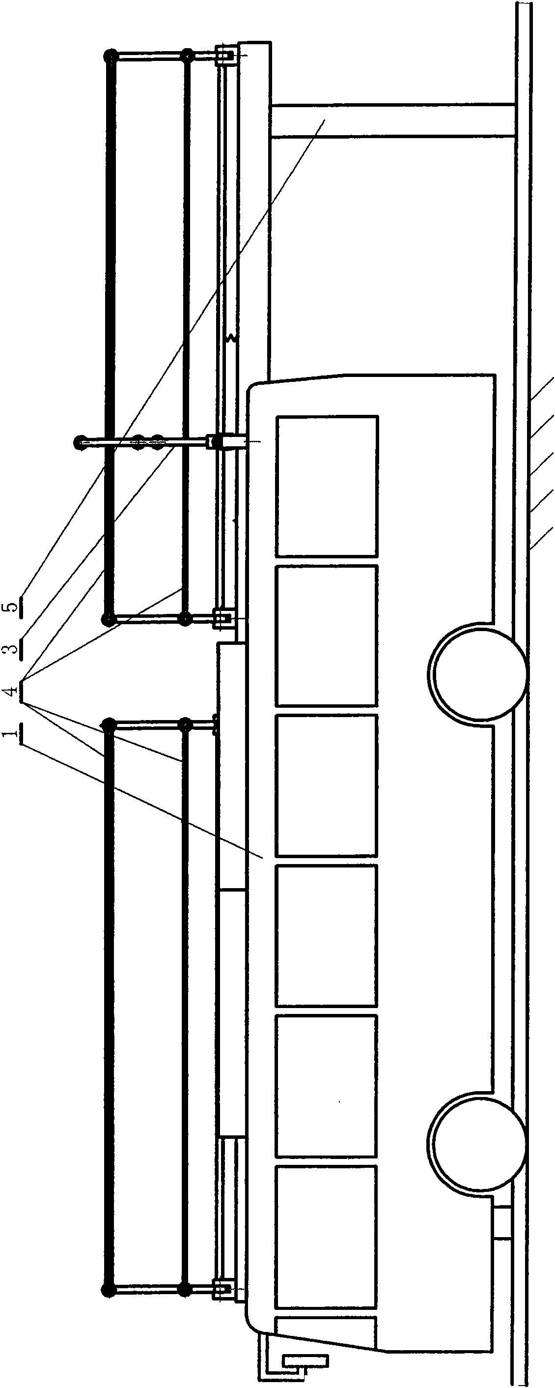
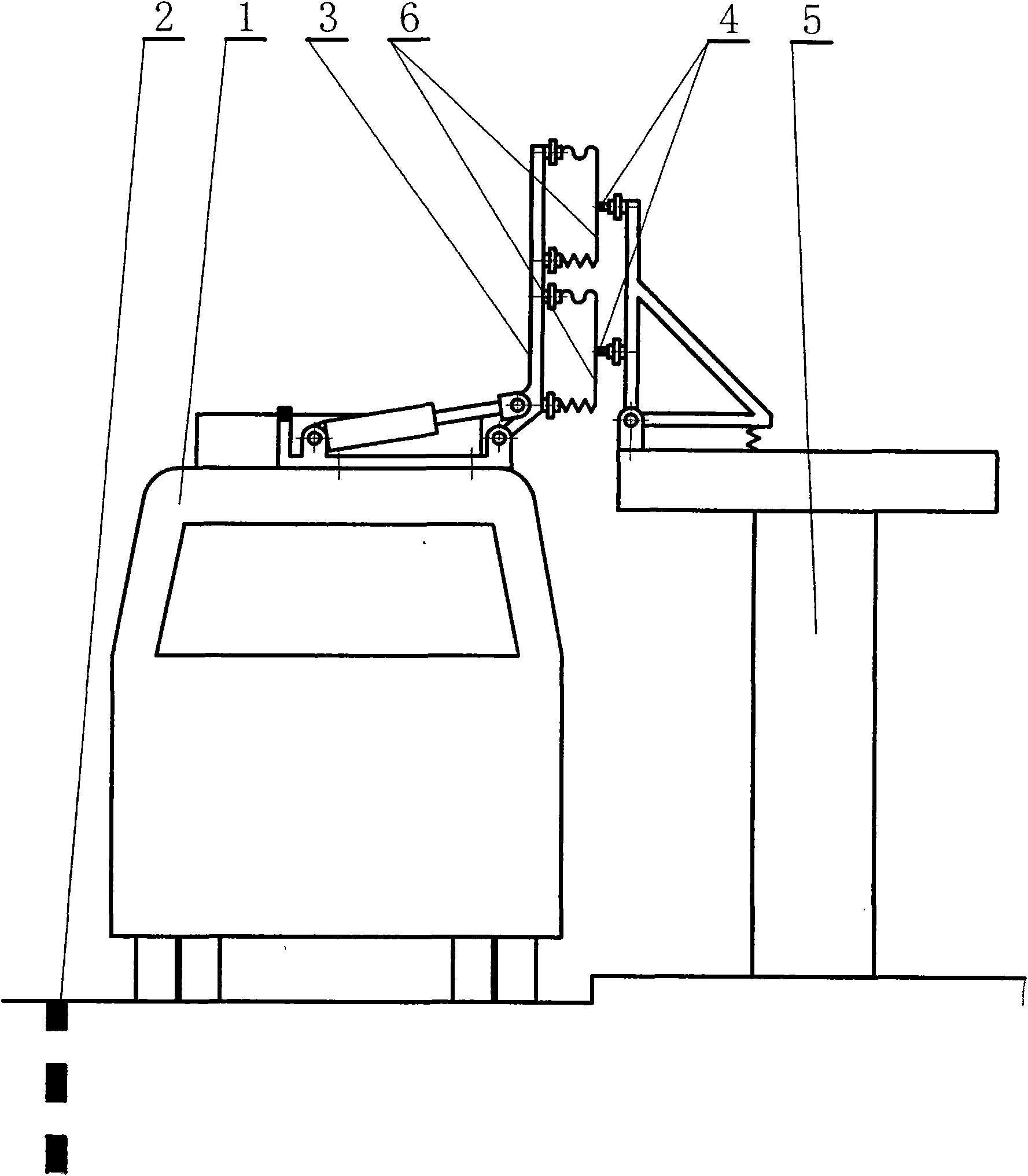
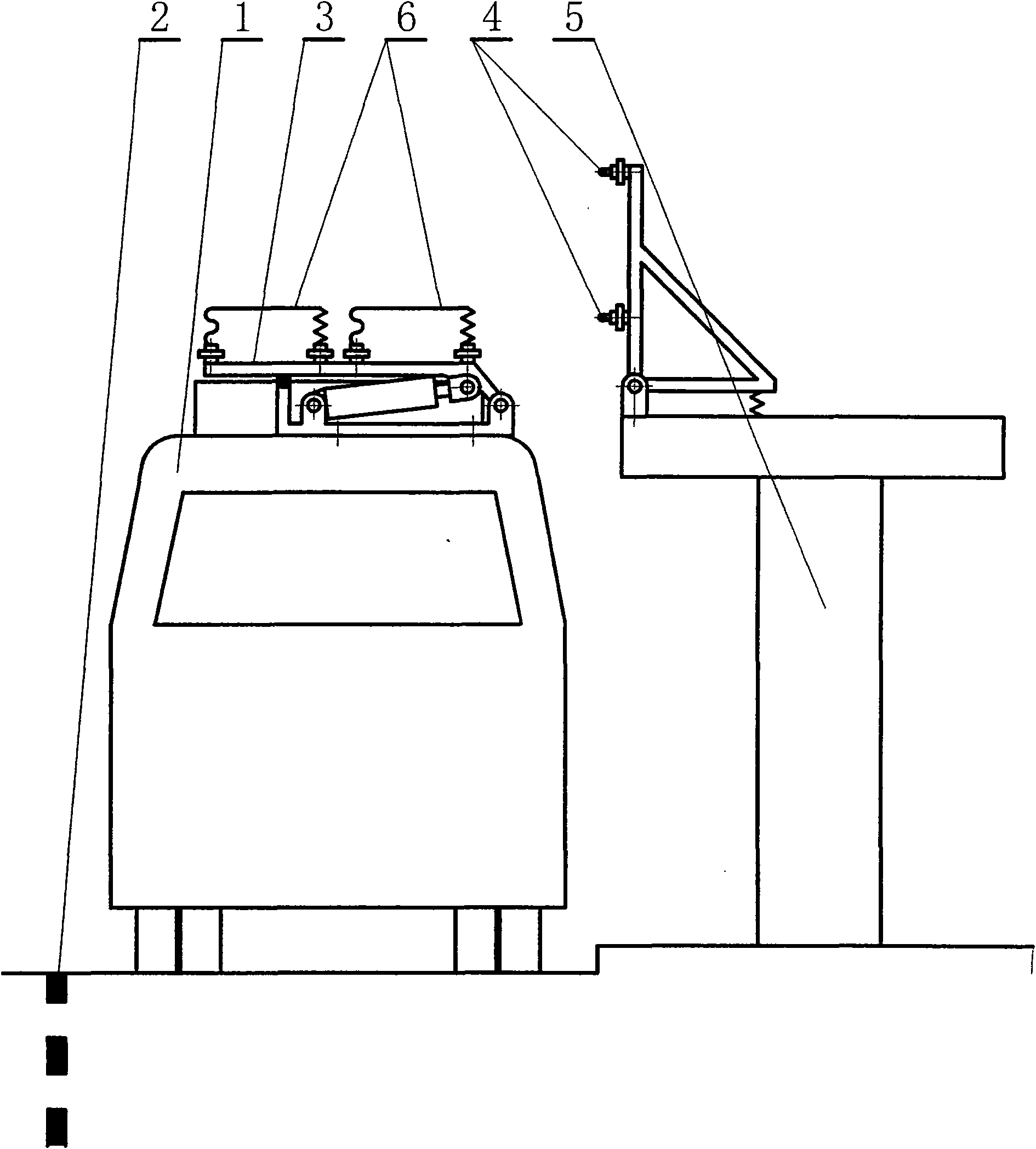
[0016] Such as figure 1, figure 2, image 3, Figure 4, Figure 5 and Figure 6 As shown, this embodiment includes: charging type bus tram 1 in the station area, ground road sign 2 in the station area, double-wire pantograph 3 receiving power laterally, double-feed wire 4, charging type bus tram waiting station 5, The rechargeable bus tram 1 in the station area is driven by a motor, with on-board storage batteries or / and supercapacitors as the driving power, and the ground road sign 2 in the station area is the station area road of the rechargeable bus tram wai...


PUM


Abstract

A station charging type public transportation trolley bus system receiving power in transverse and lateral direction comprises a station charging type public transportation trolley bus, a station surface road mark, a bi-wiring pantograph receiving power in the transverse and lateral direction, a double feeding wire, a charging type public transportation trolley bus stand; the station charging type public transportation trolley bus takes on-vehicle storage battery or/and a supercapacitor as drive power source; the station surface road mark is a traffic sign boundary line which is on the charging type public transportation trolley bus stand road and is arranged along the correct parking position; the bi-wiring pantograph receiving power in the transverse and lateral direction is arranged at the top part of charging type public transportation trolley bus or above the stand shed of the charging type public transportation trolley bus stand; the double feeding wire is correspondingly arranged above the stand shed or at the top part of the public transportation trolley bus; the station charging type public transportation trolley bus parks at the charging type public transportation trolley bus stand and enters the station surface road mark; then the bi-wiring pantograph receiving power in the transverse and lateral direction automatically extend to contact the double feeding wire in the transverse and lateral direction of the driving direction so as to receive power and to be charged. The system of the invention features simple structure, rational system composition and beautiful appearance of the stand.

Description

technical field [0001] The invention relates to a tram system in the technical field of transportation, in particular to a charging type bus trolley system in a station area receiving power laterally. Background technique [0002] At present, the bus or trolley bus using supercapacitor energy storage in the field of urban public transportation has entered commercial operation or trial operation, and its vehicle has a small amount of supercapacitor, so the vehicle is light in weight, flexible and fast, and only needs to use the terminal and Short-term fast supplementary charging when parking at some intermediate stops can drive uninterrupted on the entire operating line. Because this technology can mostly cancel the original trolleybus overhead power supply contact line network or feeder line network along the bus line, only a section of supporting power supply contact line dedicated to charging is reserved above the driving road of the terminal station and some intermediate ...

Claims


Application Information

Patent Timeline
IPC IPC(8): B60L5/19B60L5/20B60L11/18
CPCB60L11/185B60M1/36B60L5/19Y02T90/14Y02T10/7088B60M7/003Y02T10/7005B60L11/1801Y02T90/128B60L5/42B60L50/53B60L53/11Y02T10/70Y02T10/7072
Inventor 程晓鸣
Owner SHANGHAI JIAO TONG UNIV
Why Eureka
Try Eureka