Bone fracture plate formed by a vertebral plate

A laminoplasty and bone plate technology, applied in the directions of outer plate, internal bone synthesis, internal fixator, etc., can solve the problems of difficult installation and fixation, difficult reconstruction of bone graft blocks, etc. Effect

Inactive Publication Date: 2009-11-25
陈哲
View PDF0 Cites 12 Cited by
  • Summary
  • Abstract
  • Description
  • Claims
  • Application Information

AI Technical Summary

Problems solved by technology

[0024] In order to overcome the shortcomings of the prior art that the bone graft block is difficult to rebuild, difficult to install and fix, and the postoperative callus is easy to proliferate and protrude into the spinal canal, the present invention pro

Method used


Image

  • Bone fracture plate formed by a vertebral plate
  • Bone fracture plate formed by a vertebral plate
  • Bone fracture plate formed by a vertebral plate

Examples


Embodiment 1

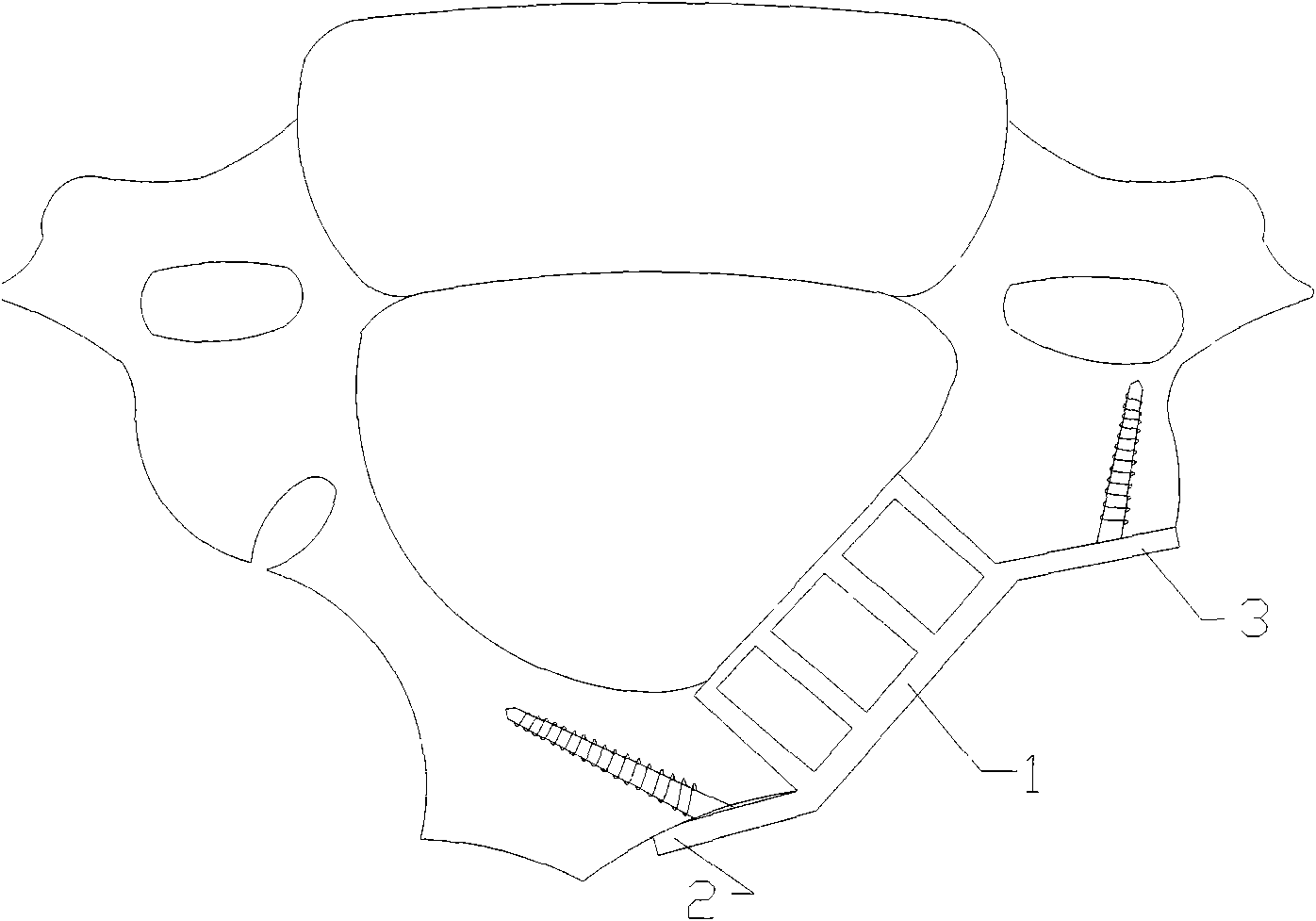
[0053] refer to Figure 3-6

[0054] The laminoplasty bone plate includes a mesh frame 1 for accommodating bone graft material, the mesh frame 1 includes a bottom surface 11 facing the inner cavity of the spinal canal, an upper side 12, and a lower side 13; the top surface of the mesh frame 1 14 has an opening for inserting and tamping the bone graft material. The inner surface 15 of the mesh frame 1 has an inner opening for the broken end of the lamina to connect with the bone graft material inside the mesh frame. The outer surface of the mesh frame 1 The side 16 has an outer opening for the side mass stump of the cervical vertebra to be connected with the bone graft material inside the screen frame 1; the inner side of the top surface of the screen frame 1 is provided with a first mounting plate 2 affixed to the broken end of the lamina, The outer side of the top surface of the screen frame is provided with a second mounting plate 3 fixedly connected to the broken end of th...

Embodiment 2

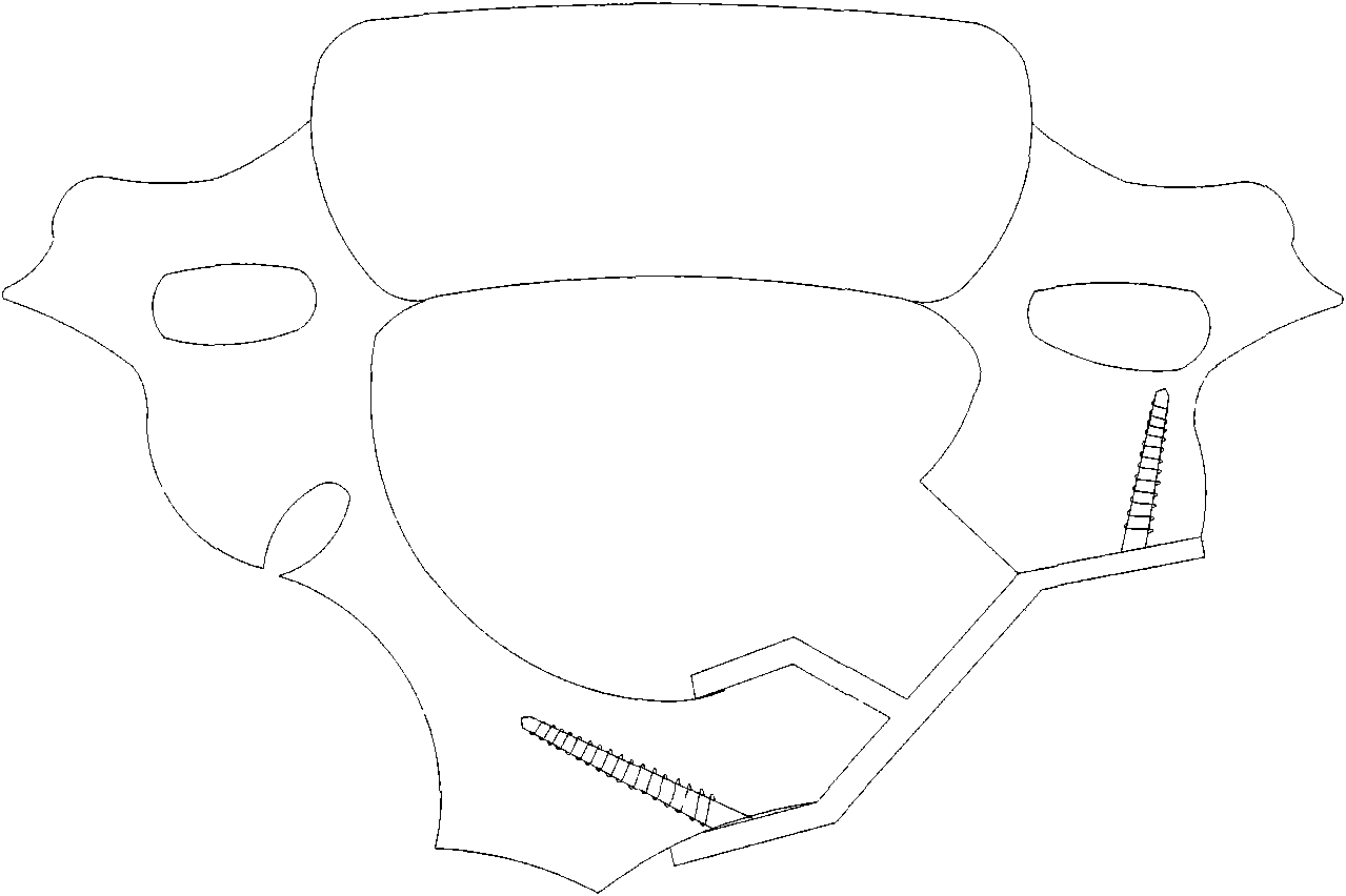
[0063] refer to image 3 , 7

[0064] The difference between this embodiment and the first embodiment is that: the bottom surface 11 of the screen frame 1 is in an arc shape matching with the segment of the spinal canal to be connected. For large-sized bone plates, the bottom surface of the mesh frame 1 is set in an arc shape to reduce the compression of the mesh frame to the inner nerves of the spinal canal.

Embodiment 3

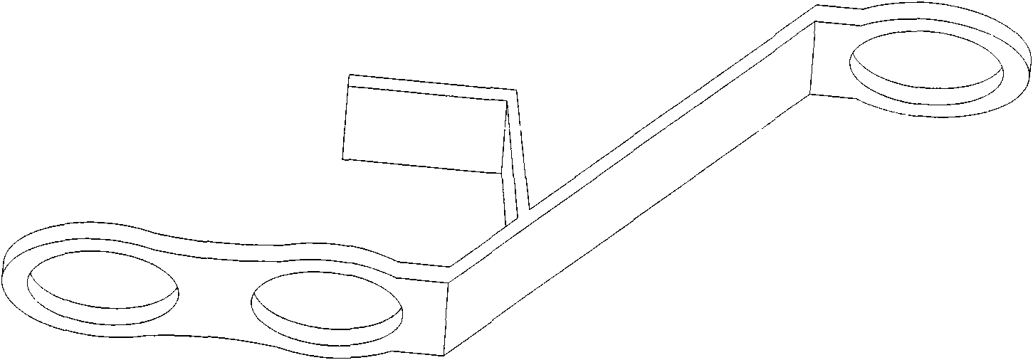
[0066] refer to image 3 , 8

[0067] The difference between this embodiment and Embodiment 1 is that for those with larger skeletons, such as adult male patients in Northeast China, a single large screw can be used for fixation. The first mounting plate is fixed to the base of the spinous process by a large screw or directly penetrated into the contralateral lamina and fixed to the stump of the lamina, and the second mounting plate is fixed to the stump of the lateral mass by a large screw. connected; the diameter of the large screw is 3.0mm or 3.5mm, and the length is 6mm or 8mm or 10mm or 12mm or 14mm.


PUM

PropertyMeasurementUnit
Diameteraaaaaaaaaa
Lengthaaaaaaaaaa
Diameteraaaaaaaaaa

Abstract

A bone fracture plate formed by a vertebral plate comprises a reticular frame for holding a bone grafting material. The reticular frame comprises a bottom surface facing to the inner cavity of a vertebral canal, an upper side face and a lower side face. The top surface of the reticular frame is used for implanting and tamping the opening of the bone grafting material. The inner side face of the reticular frame is provided with an inner opening used for the connection of the broken ends of the vertebral plate and the bone grafting material inside the reticular frame. The outer side face of the reticular frame is provided with an outer opening used for the connection of the broken ends of a lateral mass of a cervical vertebra and the bone grafting material inside the reticular frame. The inner side on the top surface of the reticular frame is provided with a first mounting plate fixedly connected with the broken ends of the vertebral plate and the outer side on the top surface of the reticular frame is provided with a second mounting plate fixedly connected with the broken ends of the lateral mass. The invention has the advantages that the invention is capable of effectively and adequately grafting bone, preventing grafted bone piece from falling into the vertebral canal after surgery, and also preventing a callus from proliferating and protruding towards the vertebral canal.

Description

technical field [0001] The invention relates to a laminoplasty osteosynthetic plate used in posterior cervical laminoplasty. technical background [0002] The most commonly used methods of cervical spine surgery are divided into two categories according to the approach of incision, anterior cervical surgery and posterior cervical surgery. [0003] Anterior cervical decompression and fusion surgery was first reported by Smith and Robinson in 1958. Anterior cervical decompression and interbody fusion is a widely accepted method for the treatment of myeloid and radicular cervical spondylosis. The purpose of decompression is to restore nerve function, and the purpose of fusion is to provide stability, prevent further nerve damage caused by abnormal intervertebral activities, maintain spinal alignment, maintain intervertebral height, maintain curative effect, and prevent recurrence. [0004] Usually, three cortical bones are chiseled from the patient's own ilium and implanted in...

Claims


Application Information

Patent Timeline
IPC IPC(8): A61B17/80A61B17/70
CPCA61B17/7071
Inventor 陈哲
Owner 陈哲
Why Eureka
Try Eureka