Gas-oil-water three-phase separating device

A three-phase separation and three-phase separator technology, applied in liquid separation, separation method, liquid degassing and other directions, can solve the problems of unsatisfactory separation effect, not very suitable, large volume, etc., achieve ideal separation effect, maintenance and repair Effortless work and improved metering effect

Inactive Publication Date: 2009-11-25
宁波威瑞泰默赛多相流仪器设备有限公司 +2
View PDF1 Cites 12 Cited by
  • Summary
  • Abstract
  • Description
  • Claims
  • Application Information

AI Technical Summary

Problems solved by technology

[0007] On the other hand, traditional three-phase separators only rely on gravity to naturally separate gas, oil, and water. The oil content in the fin

Method used


Image

  • Gas-oil-water three-phase separating device
  • Gas-oil-water three-phase separating device
  • Gas-oil-water three-phase separating device

Examples


Embodiment 1

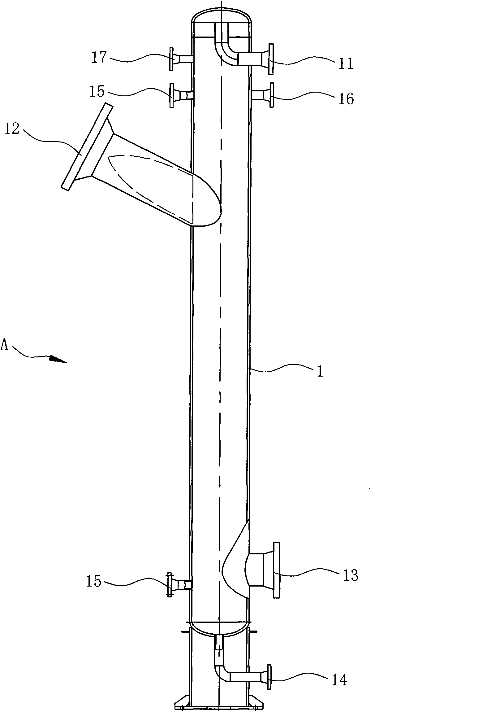
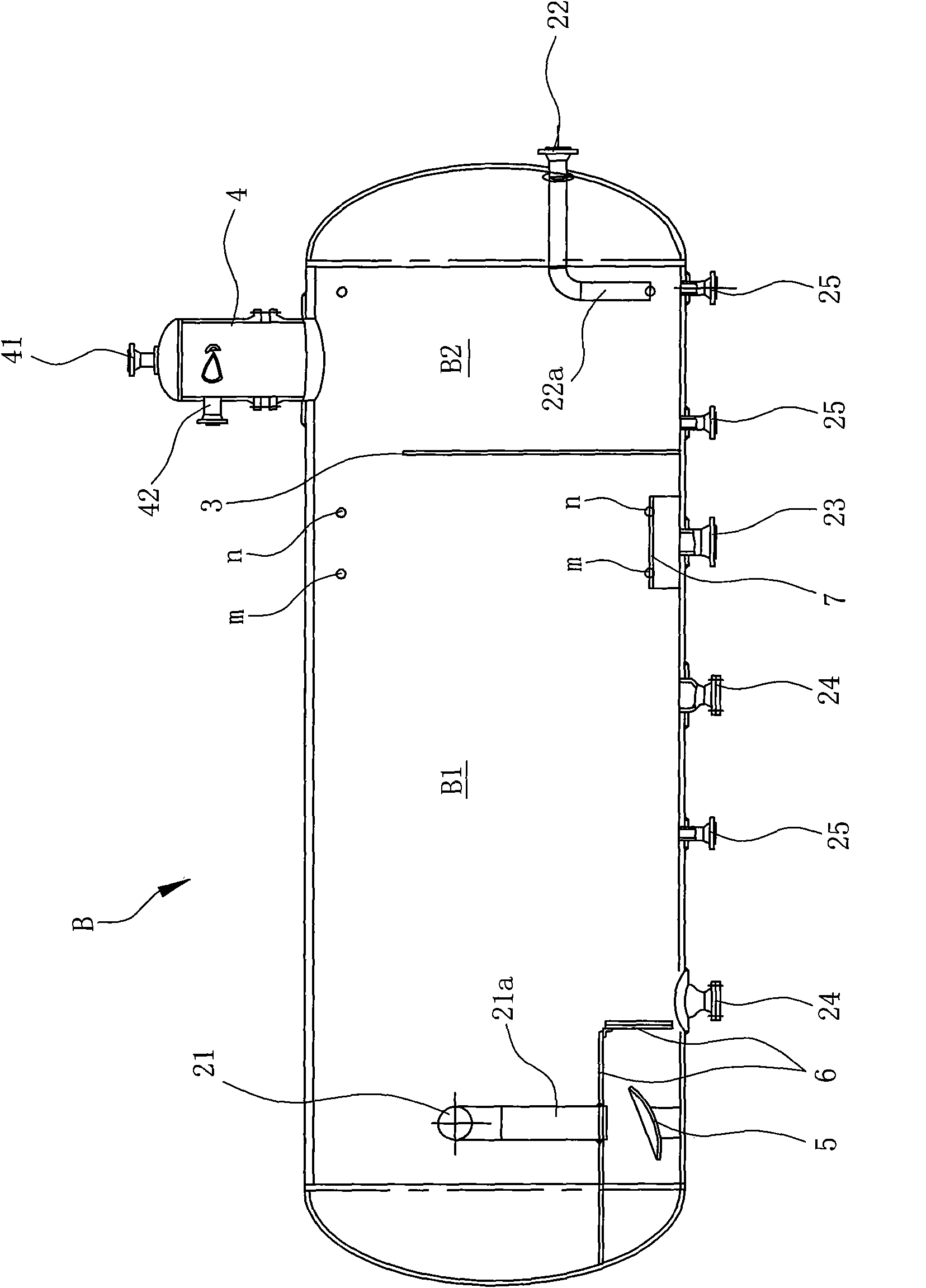
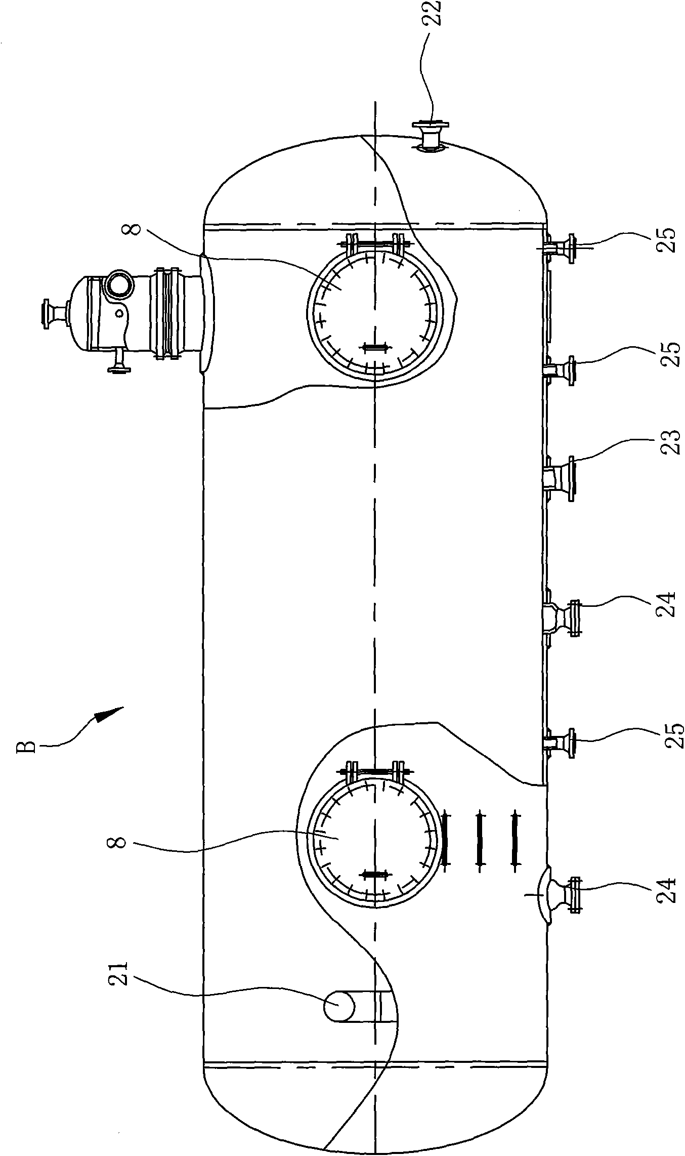
[0029] like Figure 1 ~ Figure 4 As shown, the gas-oil-water three-phase separation device includes a columnar cyclone gas-liquid separator A and a horizontal three-phase separator B communicating with the columnar cyclone gas-liquid separator A;

[0030] Wherein, the columnar cyclone gas-liquid separator A includes a columnar body 1, the upper, middle, lower, and bottom of the sidewall of the columnar body 1 are respectively provided with outlet pipes 11 communicating with the inside of the columnar body 1 , Crude oil inlet pipe 12, liquid outlet pipe 13, sewage outlet pipe 14, the connecting end of the crude oil inlet pipe 12 is inclined downward relative to the columnar cylinder 1, and is tangent to the side wall of the columnar cylinder 1;

[0031]Two liquid level transmitter pressure connection pipes 15, a temperature transmission pressure connection pipe 16 and a pressure gauge connection pipe 17 are also arranged on the cylindrical cylinder body 1, wherein the two liqui...

Embodiment 2

[0046] like Figure 5 As shown, the difference between Embodiment 2 of the present invention and Embodiment 1 is that: the crude oil inlet pipe 12 is in an inverted L shape, the end of the vertical part 12a of the crude oil inlet pipe 12 opens downward, and the horizontal direction of the crude oil inlet pipe 12 The end of the portion 12b is tangent to the side wall of the cylindrical body 1 .


PUM


Abstract

The invention discloses a gas-oil-water three-phase separating device, which comprises a columnar whirl gas-liquid separator (A) and a horizontal three-phase separator (B). The horizontal three-phase separator (B) comprises a horizontal tank (2) with a vertical baffle plate (3) which divides the inside of the horizontal tank (2) into a liquid collecting region (B1) and an oil collecting region (B2). Gap is arranged between the top of the baffle plate (3) and the top of the horizontal tank (2), the horizontal tank (2) is provided with a liquid inlet tube (21), an oil discharge tube (22), a water discharge tube (23) and a gas collecting bag (4), the liquid outlet tube (13) of the whirl gas-liquid separator (A) is communicated with the liquid inlet tube (21), and the gas outlet tube (11) of the whirl gas-liquid separator (A) is communicated with the gas collecting bag (4). The horizontal three-phase separator separates the gas phase, oil phase and water phase with a few amounts in a mixed solution through a gravity method so that the gas has single collecting space, so as to reduce the space of the gas at the top of the horizontal tank. The horizontal tank has a volume decreased by 1/3 with respect to the same raw oil treatment capability and is extremely applicable to an ocean platform.

Description

technical field [0001] The present invention relates to the technical field of gas, oil and water separation treatment, especially refers to a kind of gas-oil-water three-phase separation process, which adopts swirling flow method to separate gas-liquid and gravity method to separate gas-liquid oil, and finally realizes three-phase separation Gas-oil-water three-phase separation device. Background technique [0002] The oily water in the production process of oil and natural gas comes from various links such as oil and natural gas exploitation, processing, refining, storage and transportation. Chemical agents and some microorganisms. [0003] Generally, the physical state of oil in oily water can be roughly divided into five types: slick oil, dispersed oil, emulsified oil, dissolved oil and solid-adhered oil. Usually, the above-mentioned physical states coexist. The commonly used physical treatment methods mainly include gravity method, centrifugation method, air flotation...

Claims


Application Information

Patent Timeline
IPC IPC(8): B01D19/00B01D17/025
Inventor 王守波洪毅孙钦叶兵
Owner 宁波威瑞泰默赛多相流仪器设备有限公司
Why Eureka
Try Eureka