Plane dust collection device

A dust removal device and plane technology, applied in the direction of external electrostatic separator, electrode structure, electrostatic separation, etc., can solve the problems of cleaning, etc., and achieve the effect of simple structure, flexible electrode shape and high cleaning efficiency

Inactive Publication Date: 2009-11-25
NAT SPACE SCI CENT CAS
View PDF0 Cites 71 Cited by
  • Summary
  • Abstract
  • Description
  • Claims
  • Application Information

AI Technical Summary

Problems solved by technology

[0004] The purpose of the present invention is to provide a flat dust removal device to solve the problem of removing tiny dust deposits on the surface of materials in aerospace, industrial and civil fields. The driving voltage is a relatively low alternating current, which has low requirements on dust removal equipm

Method used


Image

  • Plane dust collection device
  • Plane dust collection device
  • Plane dust collection device

Examples


Embodiment 1

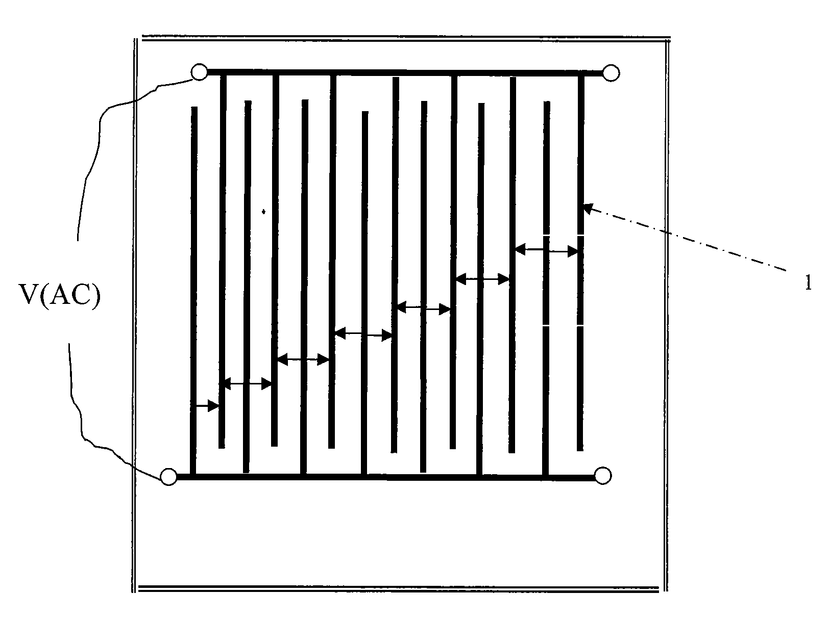
[0038] figure 2 It is a structural schematic diagram of the present invention (using comb-shaped electrodes, two-phase AC drive power supply); a pair of comb-shaped electrodes are in the same plane, and the first comb-shaped teeth 1 and the first comb-shaped teeth 2 of the pair of electrodes are opposite Placed crosswise, the cross-section width of the comb-shaped teeth is 0.1mm-1.5mm, and the spacing between the comb-shaped teeth is 0.2mm-5mm; an AC voltage of 50V-2000V (ie, the driving power V) is connected to the input end of the electrode, and the The AC voltage is a square-wave AC power source with an adjustable frequency between 50 and 500 Hz. The parallel electrodes of the planar dust removal device of this embodiment can be placed on a substrate.

Embodiment 2

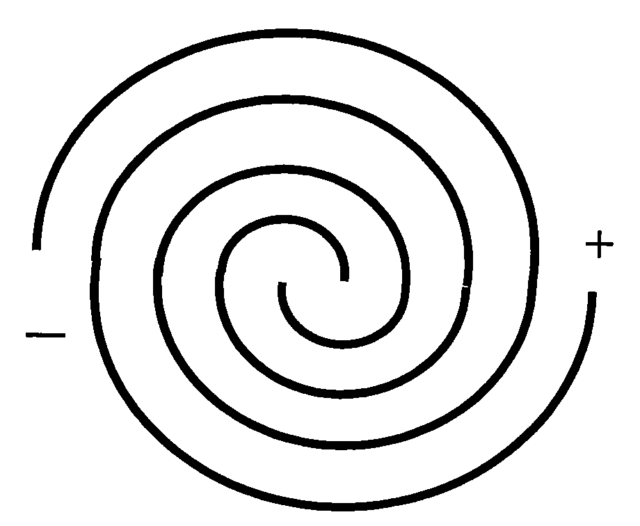
[0040] attached image 3 It is a schematic diagram of the structure of the present invention (using a spiral-shaped electrode, two-phase alternating current driving power supply); the driving power adopts two-phase electric driving, and after passing through the alternating current, the dust will be removed outside the electrode area. A pair of spiral electrodes (electrode 1 and electrode 2) are in the same plane. The two sets of spiral electrodes of the pair of electrodes are placed opposite to each other. The cross-sectional width of the spiral electrodes is 0.1mm-1.5mm, and the distance between the electrodes is 0.2mm. -5mm; a voltage of 50V to 2000V is connected to its input terminal, and the voltage is a frequency-adjustable square-wave AC power supply.

[0041] In short, as long as the parallel electrodes are covered on the surface of the equipment that needs to be dust-proof, the equipment can be kept in a dust-free environment. If transparent electrodes are used, they ...

Embodiment 3

[0044] Figure 4 It is a structural schematic diagram of the present invention (using parallel electrodes, three-phase alternating current driving power supply); its driving power is driven by three-phase electric power, and after passing through alternating current, dust will be removed outside the electrode area. Three sets of comb-shaped electrodes (electrode 1, electrode 2 and electrode 3 are in the same plane, three sets of comb-shaped teeth are placed at intervals, the cross-sectional width of the comb-shaped teeth is 0.1mm-1.5mm, and the distance between the comb-shaped teeth is 0.2 mm-5mm; a voltage of 50V-2000V (that is, a driving power supply V) is connected to its input terminal, and the voltage is a frequency-adjustable square-wave AC power supply.


PUM


Abstract

The invention relates to a plane dust collection device, which comprises at least one pair of parallel electrodes positioned in the same plane and a driving power supply for conducting AC for the parallel electrodes, wherein the parallel electrodes can be placed on a substrate; each pair of the parallel electrodes of the parallel electrodes can be formed by comb-shaped electrodes, and each pair of the comb-shaped electrodes is placed oppositely in a cross mode; each pair of the parallel electrodes of the parallel electrodes also can be formed by helical or circular electrodes; and the driving power supply is a two-phase, triphase or multiphase AC power supply. The plane dust collection device has the advantages of simple structure, flexible electrode shape, wide application range, suitability in dedusting of the surfaces of a plurality of devices and high removal efficiency on small dust.

Description

technical field [0001] The invention relates to a dust removal device, in particular to a plane dust removal device; it can be used for dust removal of solar cells or other equipment requiring dust removal in aerospace, industrial and civil fields, especially for dust accumulation on the surface of small-scale objects. Background technique [0002] Solar cells are one of the commonly used energy supply methods in aerospace, industrial and civil fields. However, there are a lot of dust on the moon, Mars and the earth. These dusts are gradually deposited on the panels of the batteries. When the dust reaches a certain level, the It will seriously reduce the energy conversion efficiency of solar cells. On the surface of optical devices such as CCD, if too much dust is deposited, it will also affect the use of equipment. [0003] The existing electrostatic precipitator used for these equipments that need to be dedusted uses a high-voltage electric field to ionize the gas, and th...

Claims


Application Information

Patent Timeline
IPC IPC(8): B03C3/04B03C3/40
Inventor 孙志斌刘雪峰王超蒋远大翟光杰
Owner NAT SPACE SCI CENT CAS
Why Eureka
Try Eureka