Cold precision forming technique of helical-spur gear and device thereof

A helical cylindrical gear, precision forming technology, applied in the direction of belt/chain/gear, gear teeth, components with teeth, etc., can solve the problems of complex helical gear tooth profile, difficult tooth profile, high forming stress of spur gear, Achieve high production efficiency, reduce final forming pressure and high precision

Inactive Publication Date: 2009-11-25
ZHENGZHOU RES INST OF MECHANICAL ENG CO LTD
View PDF2 Cites 14 Cited by
  • Summary
  • Abstract
  • Description
  • Claims
  • Application Information

AI Technical Summary

Problems solved by technology

The applicant has also studied the forming of helical cylindrical gears by two-way upsetting extrusion method, but to obtain a helical gear with full tooth profile in one step, a forming stress of about 3000 MPa is required, which also exceeds the maximum allowable stress of 2500 MPa for cold forging dies. It is the test result, so the forming s...

Method used


Image

  • Cold precision forming technique of helical-spur gear and device thereof
  • Cold precision forming technique of helical-spur gear and device thereof
  • Cold precision forming technique of helical-spur gear and device thereof

Examples


Embodiment Construction

[0028] The present invention is described below in conjunction with accompanying drawing structure, action as follows:

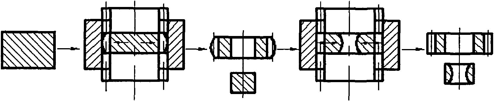
[0029] Such as Image 6 As shown: the blank 1 is put into the die 7, and the press moves downward. When the upper and lower pressing plates 11 and 8 are in contact (because the die 7 is fixed on the lower pressing plate 8), the upper and lower outer oil cylinders 13 and 3 start to discharge oil outwards. Because the die is fixed on the lower pressing plate, the die 7 starts to float downwards this moment. The upper and lower inner and outer punches 9 and 5 contact the blank 1, and start to carry out two-way extrusion on the blank 1. After a certain depth is squeezed, the oil pressure in the upper and lower inner oil cylinders 12 and 2 rises to the set oil pressure, and the upper and lower inner oil cylinders 12 and 2 Start to drain oil through the oil pipe, and now the upper and lower inner punches stop squeezing in or retreating, while the upper and lower ...


PUM


Abstract

The present invention provides a cold precision forming technique of helical-spur gear and a device thereof. The invention is characterized by adopting a cold precision forming technique that the inner punch pin and the outer punch pin are controllable and are upset-extruded bidirectionally so that the helical-spur gear can be formed to the gear with full tooth profile in one-step in the stress range allowable for the strength of the cold-forming mold material. The mould base of the special device is divided into an upper part and a lower part. The upper part is provided with an inner cylinder and an outer cylinder, a slider, an inner upper punch pin, an outer upper punch pin and an upper press plate. The lower part is provided with an inner cylinder and an outer cylinder, a cavity die, an inner punch pin, an outer punch pin and a lower press plate. When a pressing machine operates downwards, the upper press plate, the upper inner punch pin and the upper outer punch pin move downwards, the lower outer punch pin is fixed and the cavity die moves downwards. The upper inner punch pin and the lower inner punch pin are held by the pressures of the upper inner cylinder and the lower inner cylinder for squeezing out openings on the blank. After the openings are extruded to a preset depth, the upper inner punch pin and the lower inner punch pin stops the squeezing. Then the pressing machine continuously operates downwards, the upper outer punch pin and the lower outer punch pin with tooth shape start upset-extrude the blank until the final forming. The cold precision forming technique of the invention has the characteristics of one-step forming, simple technique and short flow path. The purposes of high efficiency, energy saving and material saving in cold precision forming are obtained.

Description

technical field [0001] The invention belongs to the cold precision forming process and device in the machinery manufacturing industry, in particular to a cold precision forming process and device for helical cylindrical gears, which are suitable for the production of helical cylindrical gears. Background technique [0002] At present, helical gears with large H / D (height H and diameter D) can be solved by positive extrusion method, which is not difficult in engineering, but most of helical cylindrical gears are flat, generally H / D<1 / 2~1 / 10. For flat gears, only toothed punches can be used to upset the blank in the toothed die, so that the blank can flow radially and form it, such as figure 1 As shown, since the tooth shape of the die 7 is gradually narrowed, it is quite difficult to fill the tooth shape with radial flow, or a relatively high compressive stress (up to 3000-4000Mpa) is required, so that the mold cannot bear it. The maximum allowable stress of the cold for...

Claims


Application Information

Patent Timeline
IPC IPC(8): B23F1/00B21D22/02
Inventor 刘华霍艳军孙红星刘百宣张燮昌王伟钦刘丹
Owner ZHENGZHOU RES INST OF MECHANICAL ENG CO LTD
Why Eureka
Try Eureka