Variable pitch transport chain

A conveying chain and variable pitch technology, which is applied in the field of conveying mechanisms and variable pitch conveying chains, can solve the problems of wasting mold materials, troublesome installation, high cost, etc., and achieve the effect of improving molding efficiency, saving mold materials, and outstanding effects

Active Publication Date: 2009-11-25
台州市黄岩业康机械有限公司
View PDF2 Cites 12 Cited by
  • Summary
  • Abstract
  • Description
  • Claims
  • Application Information

AI Technical Summary

Problems solved by technology

However, for blow molding machines with one out of two, one out of three, one out of four, etc., when the cylinder drives the conveyor chain to move step by step, because the step distance is two (corresponding to one out Two blow molding machines), three or four pitches (that is, the cylinder will push the preforms into the mold in groups), if the chain link pitch in the same stretch blowing unit group is still the same as that between adjacent unit groups The pitch is the same, resulting in a waste of space (because the pitch in the same stretch-blow group only needs to meet the distance between the two cavities of the mold, it does not need to be too large); and because the number of cavities on the mold corresponds to one Group of preforms, resulting in a large distance between the cavities, thus wasting mold material
In addition, when the endless conveyor chain turns and transitions, because the existing turning guide mechanism uses the tooth plate to drive the chain links, not only the friction is relatively large, but also the installation is troublesome and the cost is high

Method used


Image

  • Variable pitch transport chain
  • Variable pitch transport chain
  • Variable pitch transport chain

Examples


Embodiment Construction

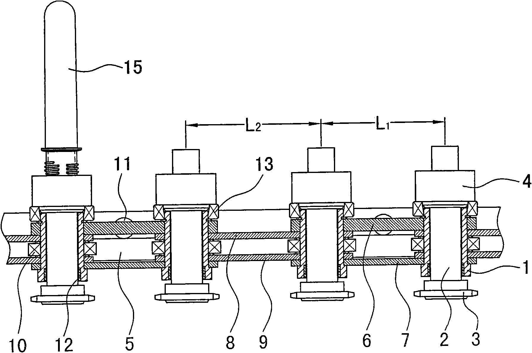
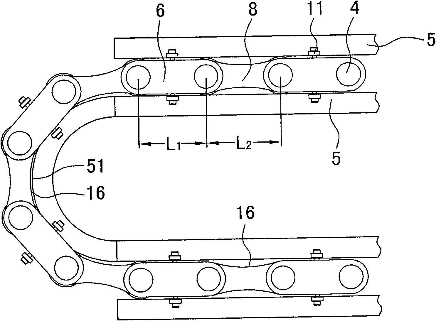
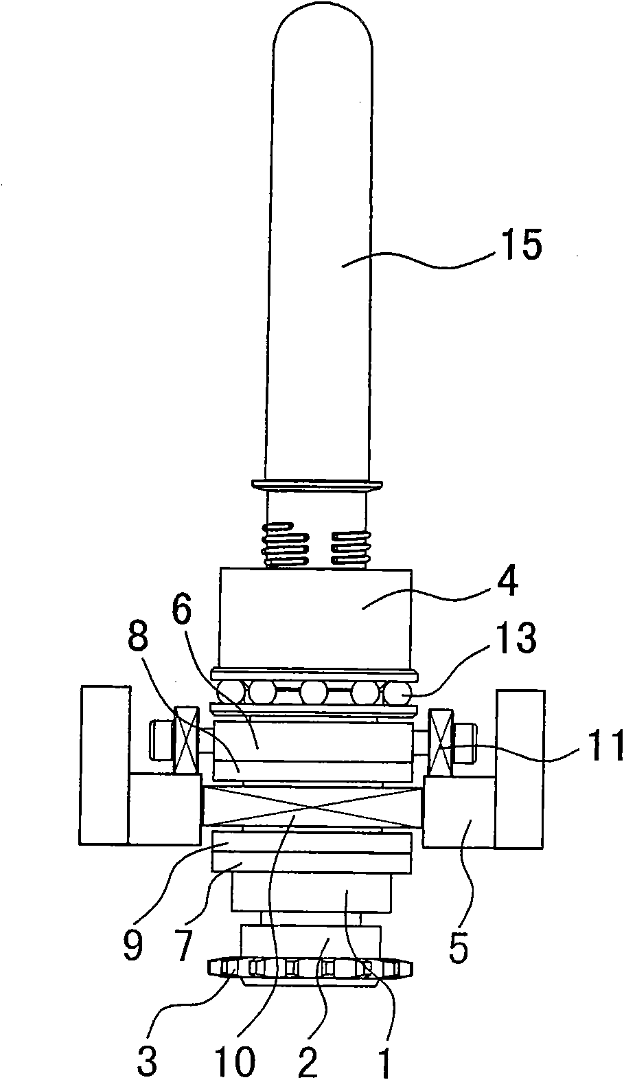
[0011] The invention discloses a variable pitch conveying chain, such as Figure 1-Figure 3 As shown, the hollow chain pin 1 is included, and each chain pin is connected by a chain plate. The hollow chain pin is equipped with a rotation shaft 2, the bottom of the rotation shaft is equipped with a rotation sprocket 3, and the upper part of the rotation shaft is equipped with a preform supporting seat 4. The preform 15 is installed on the blank supporting seat, and there are circular guide rails 5 on both sides of the conveying chain, which is characterized in that the chain links in the same stretch blowing unit group have a short pitch L 1 Less than the long pitch L of the chain link between the stretch blowing unit groups 2 , the two chain links of the short pitch are connected by the short chain plate A, B 6, 7, and the two chain links of the long pitch are connected by the long chain plate A, B 8, 9. The so-called same stretch-blowing unit group is a group of preforms form...


PUM


Abstract

The invention relates to a variable pitch transport chain which comprises hollow chain pins, wherein the chain pins are connected by chain plates; an autorotation axis is arranged in each hollow chainpin; the lower part of the autorotation axis is provided with an autorotation chain wheel, and the upper part of the autorotation axis is provided with a bottle blank supporting seat; and both sides of a transport chain are provided with annular guide rails. The variable pitch transport chain is characterized in that a chain link short pitch L1 in the same drawing and blowing unit group is smaller than a chain link long pitch L2 between the drawing and blowing unit groups; two chain links with the short pitch are connected by the short chain plate A and short chain plate B; and two chain links with the long pitch are connected by the long chain plate A and the long chain plate B. The scheme is suitable for simultaneously moulding a plurality of bottle blowing machines once and can fully and reasonably utilize a chain link space on the transport chain after the chain link pitch positioned in the same drawing and blowing unit group is shortened, thereby improving the moulding efficiency; in addition, die cavities of a moulding die correspond to bottle blanks of the same drawing and blowing unit group, after the pitch is reduced, distanc among all die cavities are also reduced, thereby saving die materials.

Description

technical field [0001] The invention relates to a conveying mechanism of a plastic hollow container stretch-blow machine, in particular to a variable-pitch conveying chain in the conveying mechanism, and belongs to the field of mechanical manufacturing. Background technique [0002] PET plastic bottles are widely used in filling various beverages, such as mineral water, juice drinks, tea drinks and dairy drinks, as well as medicine, cosmetics and other industries, which determines the broad market prospects of PET blow molding machines. PET plastic bottles are first injected with plastic raw materials into preforms by the injection molding machine, and the preforms are inserted into the preform support seat through the feeding mechanism or manually. The preform is driven by the advance type to move. The preform enters the heating zone to be heated, and then it is stretched and blown by the stretch blowing system after heating, and finally the bottle can be taken out. The pi...

Claims


Application Information

Patent Timeline
Patent Type & Authority Applications(China)
IPC IPC(8): B29C49/42B65G17/08B65G17/40B29L22/00
Inventor 柯福友
Owner 台州市黄岩业康机械有限公司
Why Eureka
Try Eureka