High precision optical fiber grating wave length demodulation system

A wavelength demodulation and fiber grating technology, applied to broadband demodulation, can solve the problems of low accuracy and signal-to-noise ratio, large bandwidth, and low cost, and achieve broad market prospects, fast response speed, and easy productization

Inactive Publication Date: 2009-11-25
BEIJING JIAOTONG UNIV
View PDF0 Cites 45 Cited by
  • Summary
  • Abstract
  • Description
  • Claims
  • Application Information

AI Technical Summary

Problems solved by technology

The accuracy of this method is limited by the stability of the light source and external interference, and it requires high stability of the FBG spectrum at the detection end; S.M.Melle et al. proposed the edge filter method in 1992, that is, a filter with a larger line width and higher transmittance The linearly changing filter is convoluted with the reflected light wavelength of the sensor FBG, and the obtained signal is proportional to the position of the FBG peak wavelength, so the FBG wavelength position can be inferred from the signal size. This method requires the edge of the demodulation filter It must be very steep and linear, requiring stable parameters of each component of the system, so it is difficult to design, manufacture and use
In 2004, Jauregui et al. proposed a demodulation method using an inclined chirped grating. The demodulator made by this method is simple in structure and small in size, but the accuracy and signal-to-noise ratio are not high
[0009] There are many fiber grating wavelength demodulation methods, but due to the respective limitations of these technologies, there are not many products put into practical application, and there is no demodulation solution that can simultaneously meet the requirements of high frequency, large bandwidth, combined measurement of dynamic and static parameters and Inexpensive requirements

Method used


Image

  • High precision optical fiber grating wave length demodulation system

Examples


Embodiment Construction

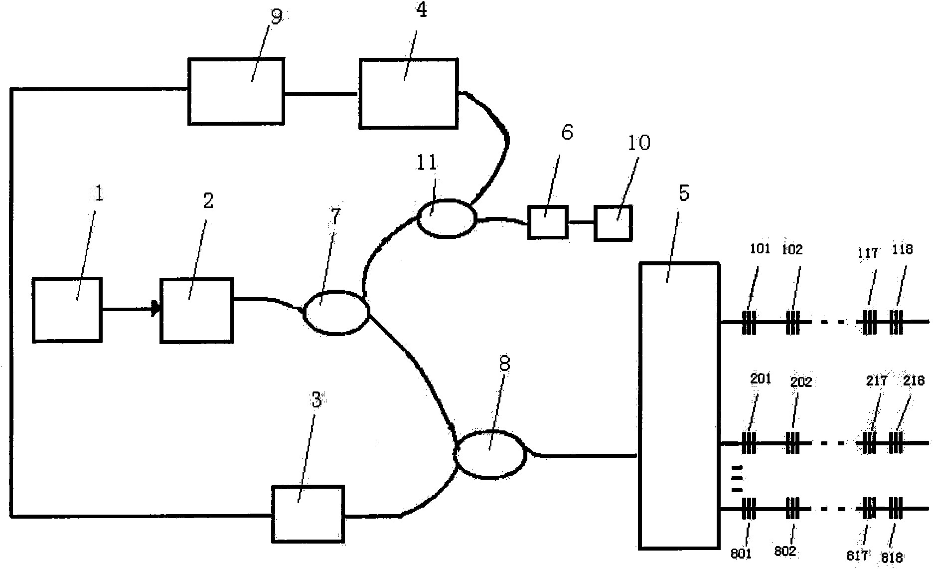
[0027] A fiber grating wavelength demodulation system, the demodulation system includes: a broadband light source 1, a tunable filter 2, a first 1×2 coupler 7, a 1×2 coupler 11, an etalon filter 6, a reference grating 10 and the wavelength calibration module composed of the second photodetector 4, the second 1×2 coupler 8, the first photodetector 3, the 1×N optical switch 5, and the signal processing system 9; the connection between the devices formed by it :

[0028] The output terminal of the broadband light source 1 is connected to the input terminal of the tunable filter 2, the output terminal of the tunable filter 2 is connected to the input terminal of the first 1×2 coupler 7, and the other output terminal of the first 1×2 coupler 7 is connected to the second An output end of the second 1×2 coupler 8; the other output end of the second 1×2 coupler 8 is connected to the signal processing system 9 through the first photodetector 3; the input end of the second 1×2 coupler 8...


PUM


Abstract

An optical fiber grating wave length demodulation system belongs to the technical field of optical fiber sensing and optical measurement. The demodulation system comprises a broad band light source (1), a tunable filter (2), a 1x2 coupler, a wave length calibration module, a photodetector, a 1xN optical switch (5) and a signal processing system. The inside connection of the wave length calibration module is that: one end of a standard tool filter (6) is connected with an output end of a third 1x2 coupler (11)m the other end of the standard tool filter is connected with a reference grating (10), an input end of the third 1x2 coupler is connected with an output end of a first 1x2 coupler; the other output end of the third 1x2 coupler is connected with a signal processing system (9) by a second photodetector (4) to implement the wave length calibration. The calibration of the reflected optical fiber grating wave length can be implemented rapidly and accurately by the standard tool filter and the reference grating, the signal can be effectively demodulated for high precision. The system also can be used for monitoring temperature and stress and so on physical quantities.

Description

technical field [0001] The invention belongs to the technical fields of optical fiber sensing and optical measurement, and relates to a fiber grating wavelength demodulation system. Especially suitable for high-precision, broadband demodulation, combined measurement of dynamic and static parameters. Background technique [0002] Fiber Bragg grating sensor has the characteristics of high reliability, anti-electromagnetic interference, anti-corrosion, etc. Its wavelength coding characteristics and the advantages of quasi-distributed measurement on a single optical fiber are unmatched by other sensors, and it has broad application prospects. One of the most important obstacles restricting the large-scale practical application of FBG sensors is the demodulation of the wavelength signals of FBG sensors. [0003] In the fiber grating sensing system, the external physical quantity is transmitted by the reflection wavelength of the fiber grating. Therefore, the wavelength demodulat...

Claims


Application Information

Patent Timeline
Patent Type & Authority Applications(China)
IPC IPC(8): G01J9/00G01D5/30
Inventor 何大伟王永生王涛王子谦
Owner BEIJING JIAOTONG UNIV
Why Eureka
Try Eureka