
Container type super power load box

A super-high-power, container-type technology, applied in the direction of measuring devices, motor generator testing, power supply testing, etc., can solve problems such as inconvenient use, high surface temperature of devices, and open flames, etc., to ensure safety, high integration power, and convenience The effect of assembly and control

Inactive Publication Date: 2009-11-25
朱晓明
View PDF0 Cites 15 Cited by
  • Summary
  • Abstract
  • Description
  • Claims
  • Application Information

AI Technical Summary

Problems solved by technology

[0006] Disadvantages: 1) The volume is large, and the device is fixed and cannot be moved
The pure water system is more complex and cumbersome
[0008] 3) Inconvenient to use
[0011] Disadvantages: The surface temperature of the device is high, and it will be hot and red when working, and an open flame will be generated. When high-power integration is to be realized under a specific volume condition, the overall temperature will rise sharply under the action of heat radiation between various components, so it is necessary for cooling The system requirements are particularly high. If the cooling system breaks down and fails to dissipate heat in time, it is very easy to cause serious safety accidents such as burning and explosion.
[0012] In short, due to the limitation of load components, the existing ultra-high-power load boxes are bulky, complicated to operate, have particularly high requirements on the cooling system, and are not high enough in safety and reliability.
The use of containers to make ≥ 4000KVA ultra-high-power load boxes meets the requirements of small size and large power for easy transportation, and at the same time, it must dissipate heat in time. Using ordinary chromium-nickel alloy or iron-chromium-aluminum alloy resistors as load elements to make such a high-power load box Load boxes, neither domestic nor foreign have any successful precedents
Usually, in the application of PTC, the power is only tens of W to several (1-2) KW, which cannot be applied to super-high-power load boxes.

Method used


Image

  • Container type super power load box
  • Container type super power load box
  • Container type super power load box

Examples


Embodiment Construction

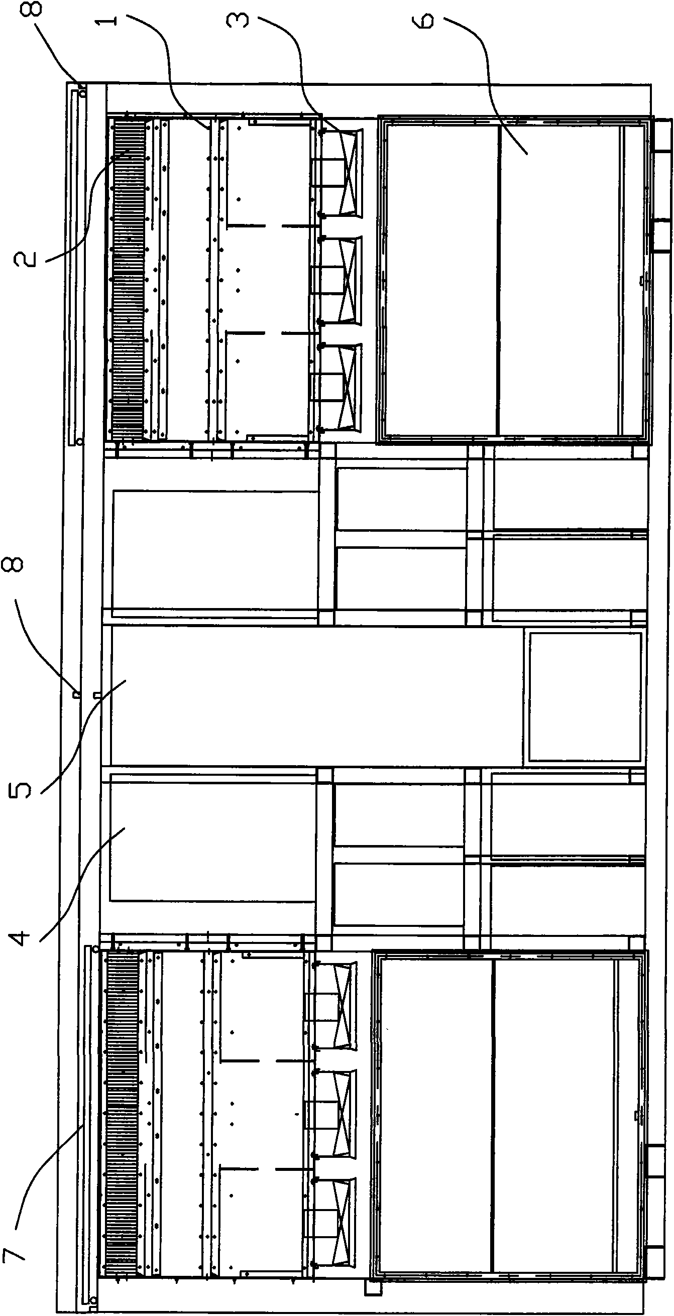
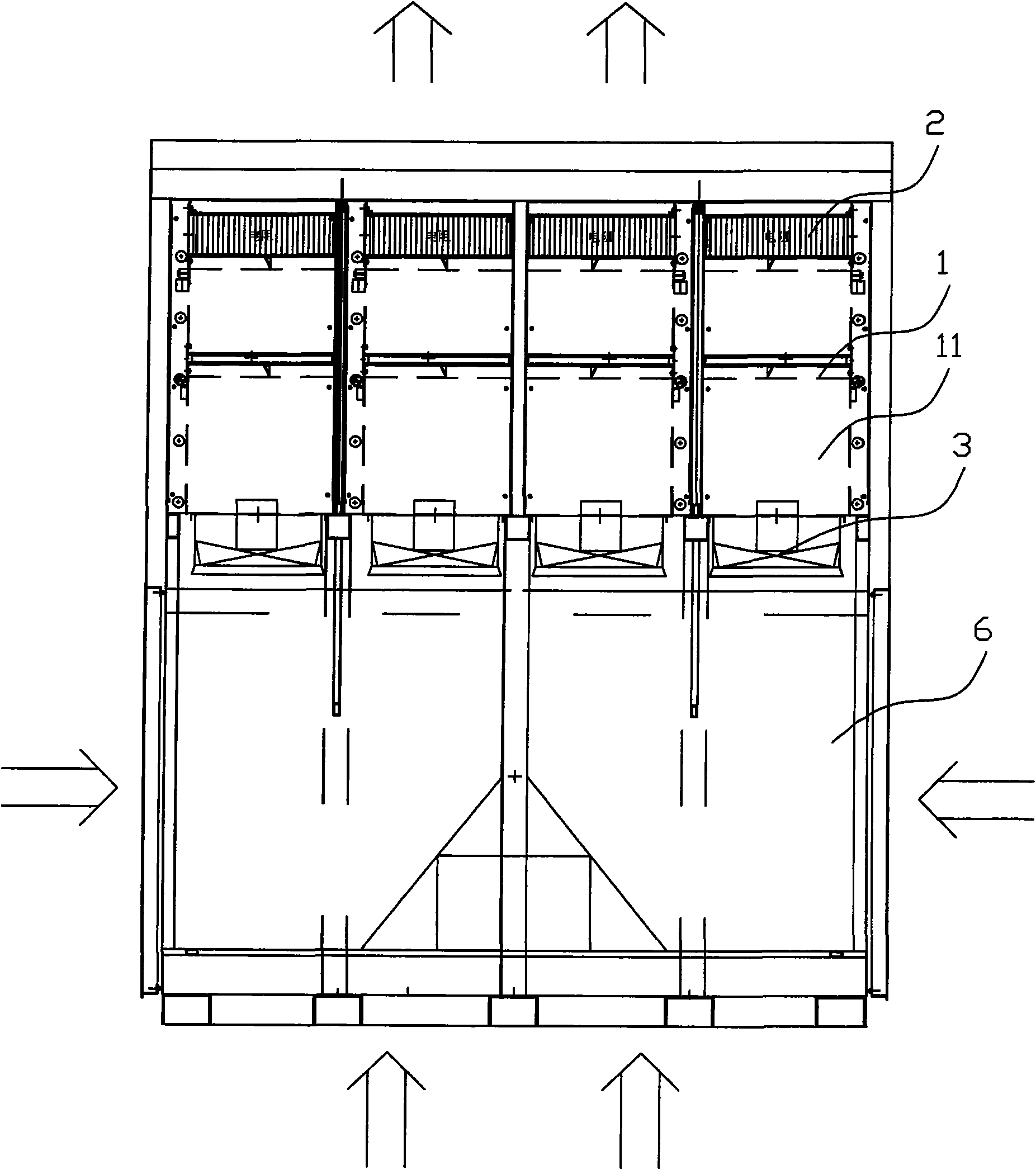
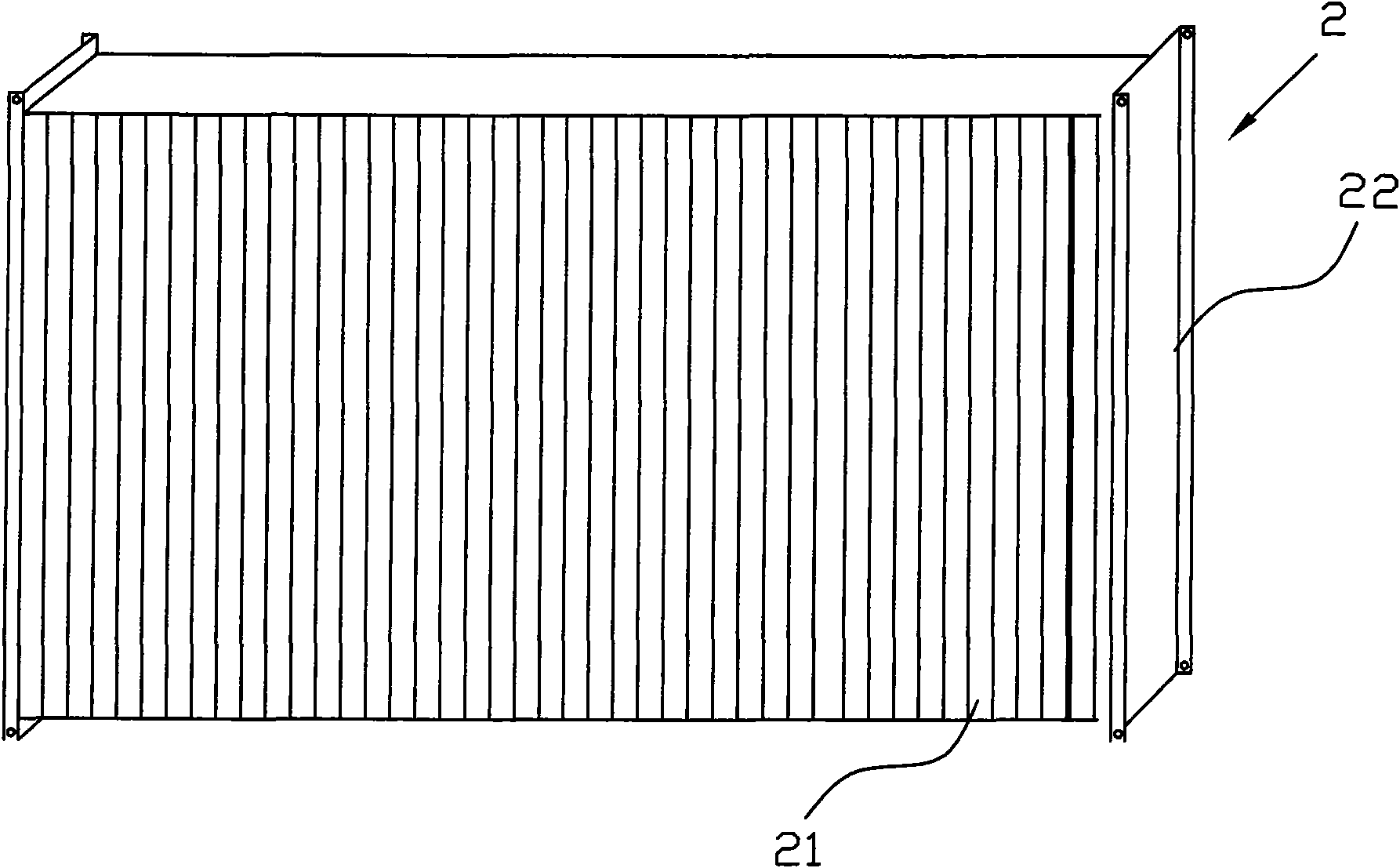
[0026] Such as Figure 1 to Figure 4 As shown, it is an embodiment of the present invention, and the load power of the ultra-high-power load box made of a 20-foot standard container is 4000KVA. The standard container is provided with 8 independent resistance boxes 1, and the resistance boxes are arranged on the upper part of the container. The size of each resistance box is 1440*900*470mm, and there are two PTC integrated resistors 2, and the integrated power reaches 500KW. The length of each PTC integrated resistor 2 is 660 mm, the height is 126 mm, and the width is 450 mm. Vertical ventilation gaps 21 are evenly provided between the resistor sheets of the PTC integrated resistor 2 . The PTC integrated resistor 2 is arranged on the resistor bracket 22, and the resistor bracket is fixed on the inner wall of the resistor box. The PTC integrated resistor is electrically connected with the power distribution system 4 and the control system 5 . The power distribution system and ...


PUM

PropertyMeasurementUnit
Axial dimensionaaaaaaaaaa
Diameteraaaaaaaaaa

Abstract

The invention discloses a container type super power load box comprising a container and a resistance box at upper portion of the container. PTC integrated resistors mounted in the resistance box are connected electrically with a power distribution system and a control system. The resistance box is further provided with a plurality of fans at lower portion. An air channel is arranged between the fan and the load resistor. Air inlets are arranged on side wall or bottom of the inlet chamber. Outlets are arranged at upper portion of resistance box on the container wall. The whole device is composed of the PTC integrated resistors and an independent resistance box module forcing wind cool, control and power distribution module, which is convenient to assemble and control. Once cooling system malfunctions, surface temperature of large power load element does not exceed 250 DEG. C with no visible light. Under extreme condition, the system can cut current automatically and severe accidents of combustion do not occur.

Description

technical field [0001] The invention relates to a container-type super-high-power load box. Background technique [0002] The ultra-high-power load box is used as a simulated load in large-scale generators, high-power UPS, inverter power supplies, and large-scale storage battery systems, and can complete the detection of system parameters and functions. [0003] The high-power load element in the super-high-power load box is an important part of the load box, and it is the key to enabling the equipment to realize functions such as miniaturization, multi-function, and flexibility. Currently commonly used load elements are: [0004] 1. Water resistance: [0005] In a large pool filled with pure water, an electrode forming resistor is placed as a load element. [0006] Disadvantages: 1) The volume is large, and the device is fixed and cannot be moved. [0007] 2) A large amount of water is evaporated during operation and must be replenished at any time. The purity of water ...

Claims


Application Information

Patent Timeline
IPC IPC(8): G01R1/20G01R31/34G01R31/40G01R31/36
Inventor 张玉华
Owner 朱晓明
Learn More