
Synchronous rectification driving circuit suitable for central tapped structure rectifying circuit

A drive circuit and rectifier circuit technology, applied in the direction of converting AC power input to DC power output, electrical components, output power conversion devices, etc., can solve the problems of increasing online loss, reducing efficiency, voltage spikes, etc., and achieve power consumption The effect of reducing, reducing costs and reducing losses

Active Publication Date: 2009-11-25
INVENTRONICS HANGZHOU
View PDF0 Cites 9 Cited by
  • Summary
  • Abstract
  • Description
  • Claims
  • Application Information

AI Technical Summary

Problems solved by technology

In the existing technology, the synchronous rectifier tube of the center-tap rectification circuit driven by the current driving method needs two current transformers as independent sampling and driving, and the cost is relatively high
Moreover, since the current transformer is connected in series with the synchronous rectifier tube, the transformer itself has some leakage inductance, which resonates with the junction capacitance between the drain and source of the MOSFET, causing voltage spikes, increasing online losses, and reducing efficiency

Method used


Image

  • Synchronous rectification driving circuit suitable for central tapped structure rectifying circuit
  • Synchronous rectification driving circuit suitable for central tapped structure rectifying circuit
  • Synchronous rectification driving circuit suitable for central tapped structure rectifying circuit

Examples


Embodiment 1

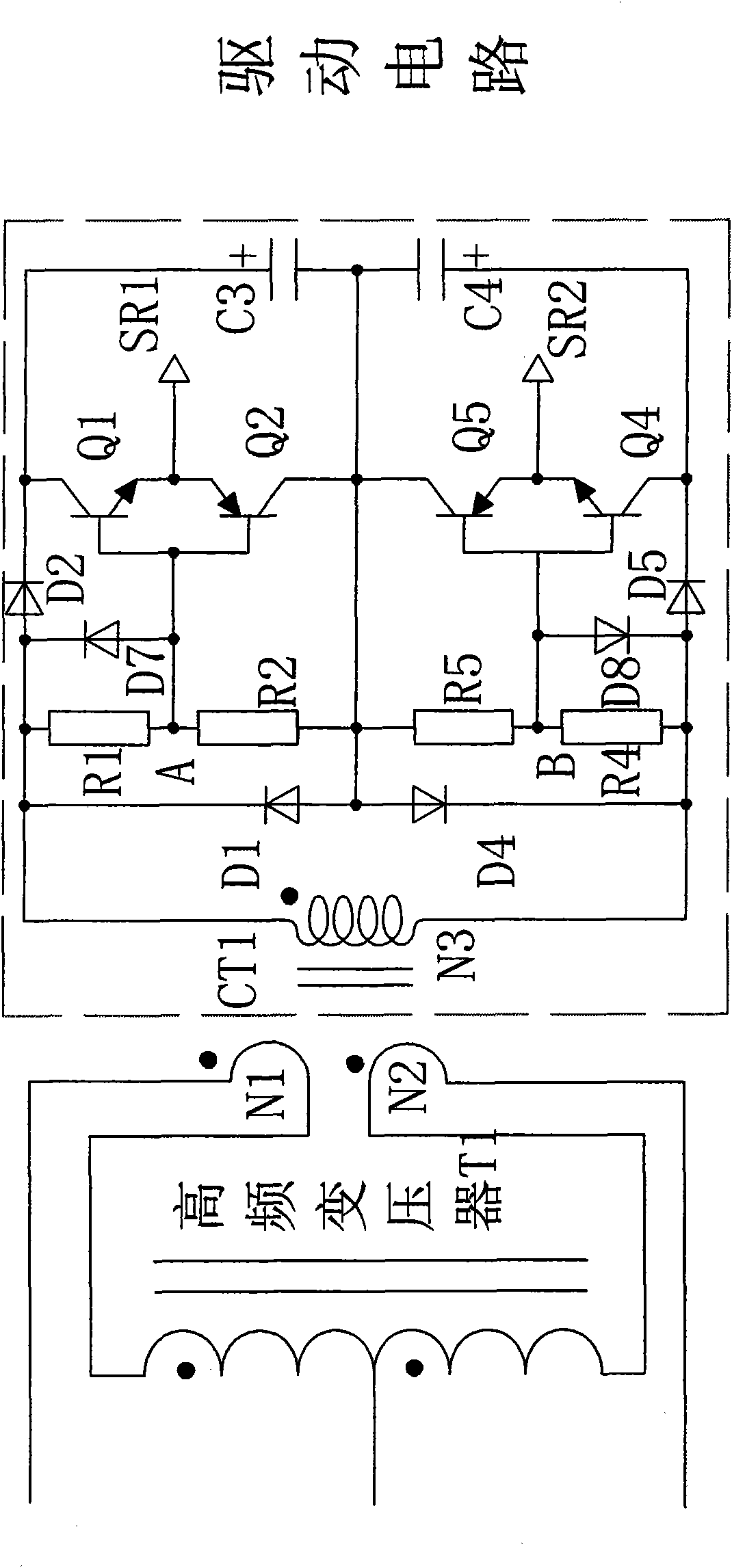
[0046] Refer to attached Figure 7 , The present invention is applied to Embodiment 1 of a center-tap structure rectifier circuit with misdrive protection, including a main circuit, a drive circuit, a current transformer CT1 and two misdrive protection circuits.

[0047] The main circuit is composed of a high-frequency transformer T1, a primary winding of a current transformer CT1, an output capacitor C1, an output capacitor C2, a synchronous rectifier SR1, and a synchronous rectifier SR2. The terminal with the same name of high-frequency transformer T1 is connected to the non-identical terminal of primary winding N1 of current transformer CT1, the non-identical terminal of high-frequency transformer T1 is connected to the terminal of the same name of primary winding N2 of current transformer CT1, and the center tap of high-frequency transformer T1 Connect to the positive poles of output capacitor C1 and output capacitor C2; the same-named terminal of the primary winding N1 of...


PUM


Abstract

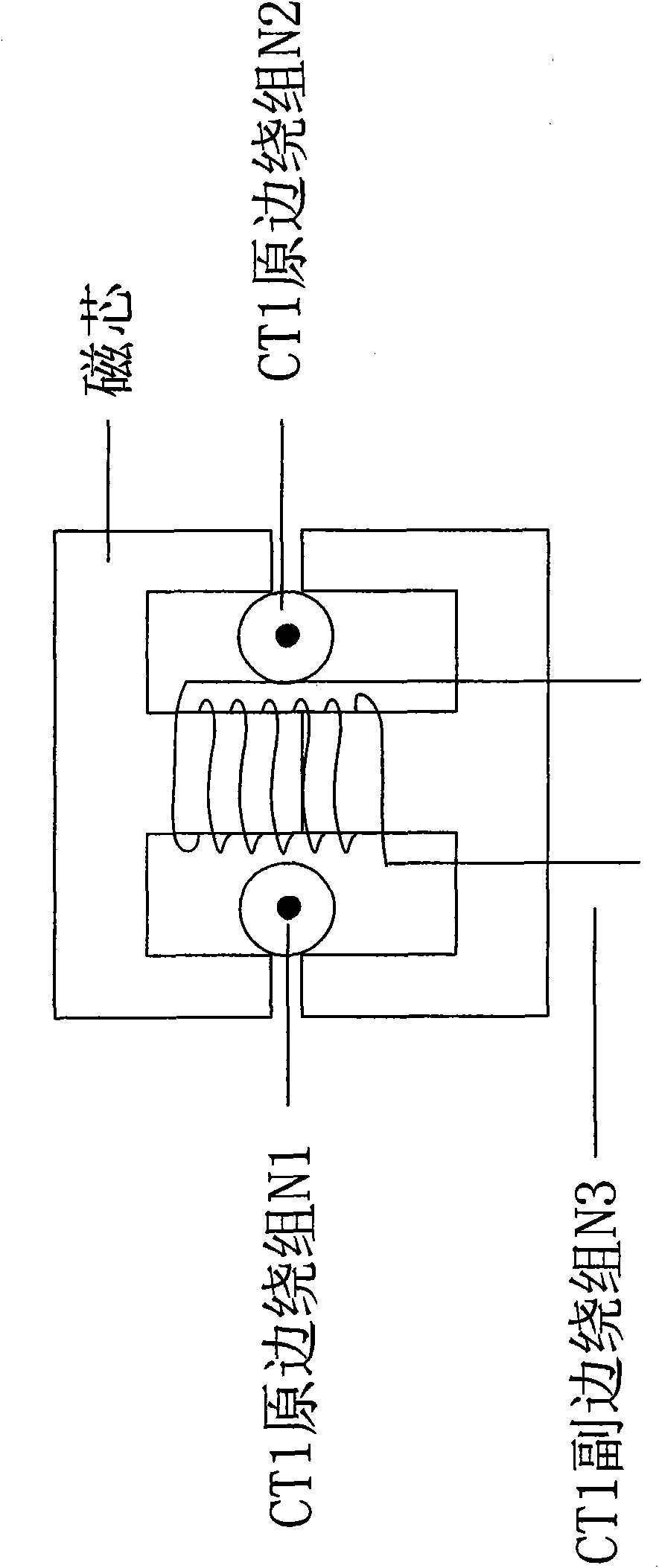
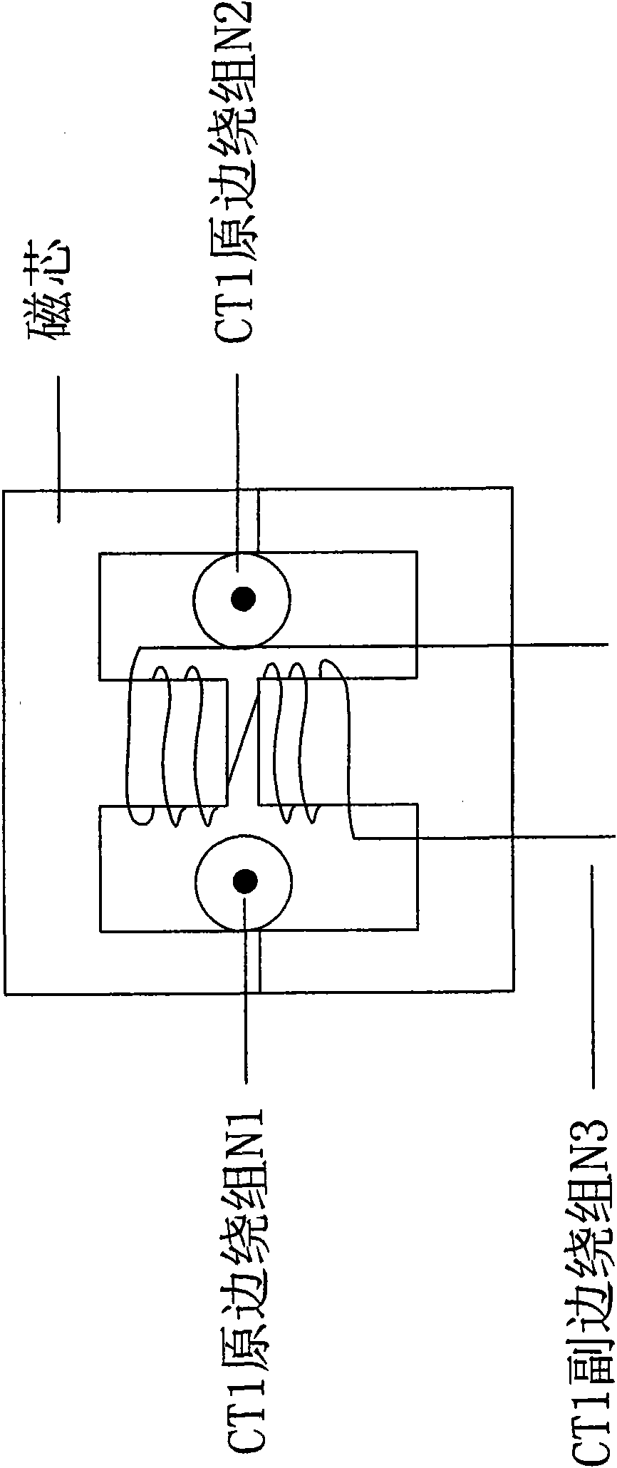
The invention discloses a synchronous rectification driving circuit suitable for central tapped structure rectifying circuit, comprising a high frequency transformer T1, a current transformer CT1, an output capacitor C1, an output capacitor C1, a synchronous rectifying tube SR1, a synchronous rectifying tube SR2 and a driving circuit for driving the synchronous rectifying tube SR1 and the synchronous rectifying tube SR2, wherein the current transformer CT1 has two primary side windings N1, N2 and one secondary side winding N3, which can drive two synchronous rectifying tubes. The favourable effects of the invention are as follows: 1, it only needs one currant transformer and one secondary side winding to realize the driving of two SRs so as to simplify the circuit and reduce the cost; and thus it is good for the high frequency and integrated development; 2, it is able to realize supplying power by itself of the driving circuit; the driving is simple; 3, it reduces the driving power consumption of the synchronous rectification, improves the light loading efficiency, reduces the loss and lowers the cost.

Description

technical field [0001] The invention relates to a synchronous rectification driving circuit. More specifically, the present invention relates to a current-controlled synchronous rectification driving circuit suitable for a center-tap structure rectification circuit. Background technique [0002] In order to reduce the power consumption of integrated circuits, the power supply voltage will be further reduced, and more and more low-voltage and high-current power supplies will be used. With the advancement of semiconductor technology, the on-resistance of low- and medium-voltage MOSFETs is getting smaller and smaller. Therefore, in low-voltage and high-current switching power supplies, in order to reduce the conduction loss, synchronous rectification technology is generally used. [0003] Synchronous rectification technology can be divided into voltage drive and current drive according to its drive signal type. Different topologies have different driving methods in the voltag...

Claims


Application Information

Patent Timeline
Patent Type & Authority Applications(China)
IPC IPC(8): H02M7/217
Inventor 吴新科郭晓君
Owner INVENTRONICS HANGZHOU
Learn More