Synchronizing ring of a synchronizing device

A technology of synchronous device and synchronous ring, which is applied in the field of synchronous ring, can solve problems such as synchronous ring failure, and achieve the effect of low-cost manufacturing, high load capacity, and no need for post-processing

Inactive Publication Date: 2009-11-25
SCHAEFFLER TECH AG & CO KG
View PDF12 Cites 11 Cited by
  • Summary
  • Abstract
  • Description
  • Claims
  • Application Information

AI Technical Summary

Problems solved by technology

If the support rings and friction elements are not after-treated, then during the shifting operation of the synchronizer, some friction elements are more strongly loaded than others, which can lead to failure of the synchronizer ring

Method used


Image

  • Synchronizing ring of a synchronizing device
  • Synchronizing ring of a synchronizing device
  • Synchronizing ring of a synchronizing device

Examples


Embodiment Construction

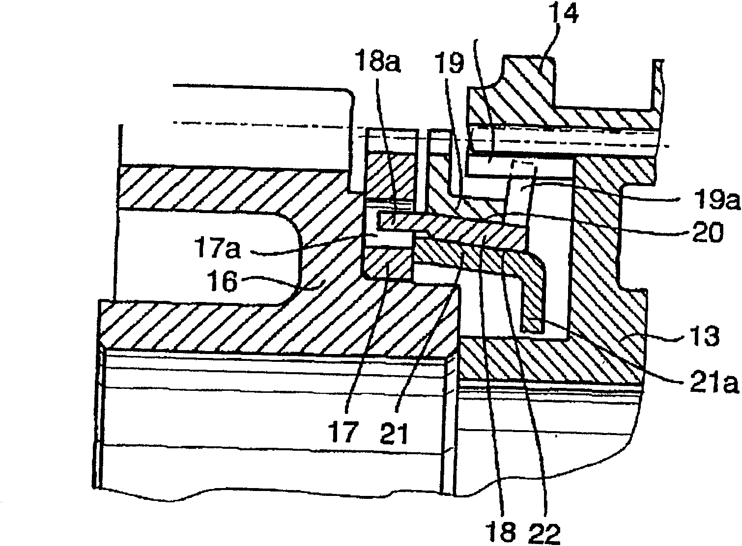
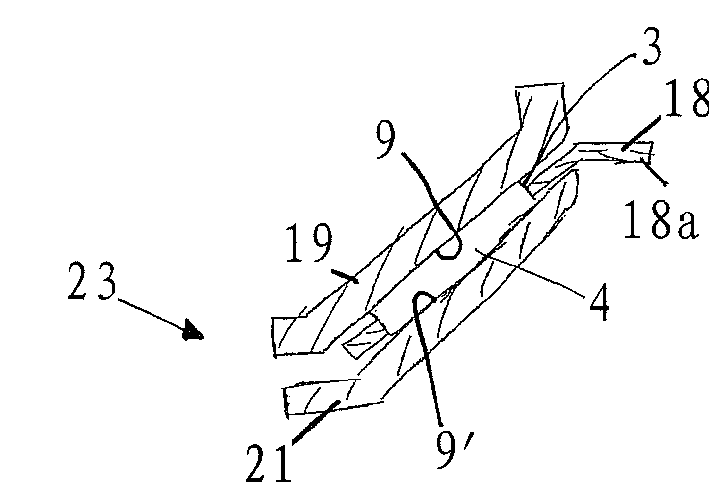
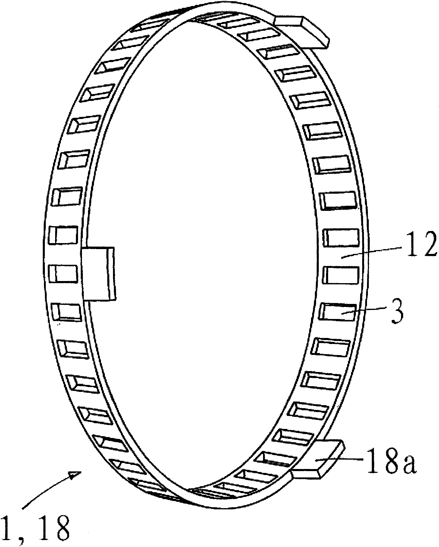
[0026] figure 1 By way of example, a synchronizing device with an outer synchronizing ring 19 , a central synchronizing ring 18 and an inner synchronizing ring 21 is shown. The synchronizing body 13 is fastened with internal toothing for a non-rotatable arrangement on the drive shaft. A driven wheel 16 is arranged next to the synchronizing body 13 . The clutch main body 17 is connected with the driven wheel 16, and the synchronous projection 18a of the intermediate ring 18 is embedded in the recess 17a of the clutch main body. The intermediate ring 18 forms a first friction pair 20 with the mating friction surface 9 of the outer synchronizing ring 19 as mating cone 8, and forms a second friction pair 22 with the mating friction surface 9' of the inner synchronizing ring 21. The mating friction surfaces 9 and 9' are not post-treated. The connection of the driven wheel 16 and the synchronizing body 13 is realized through a sliding sleeve 14 .

[0027] The inner edge 21 a of ...


PUM


Abstract

A synchronizing ring (1) for a synchronizing device of a motor vehicle gearing, with a ring body (2), wherein the ring body (2) has a plurality of recesses (3), and frictional elements (4) are arranged in the recesses (3).

Description

technical field [0001] The invention relates to a synchronizing ring of a synchronizing device of a motor vehicle transmission, having an annular body with a plurality of grooves, wherein friction elements are arranged in the grooves. Background technique [0002] Synchronizing rings of motor vehicle transmissions are usually formed by friction rings of conical configuration, which have friction surfaces on their inner side or on their outer side. If the friction ring has friction surfaces on both sides, it is also referred to as an intermediate ring. During the synchronization process, the friction surfaces of the intermediate ring are connected on the outer side in a frictional fit with friction surfaces formed on the outer synchronization ring. At the same time, the friction surface formed on the inner side of the intermediate ring is frictionally connected to the friction surface of the inner synchronizing ring. The outer synchronizing ring is positively connected to t...

Claims


Application Information

Patent Timeline
Patent Type & Authority Applications(China)
IPC IPC(8): F16D23/02F16D69/04
CPCF16D23/04F16D23/025F16D2023/0637F16D23/02F16D69/04
Inventor 托马斯·卡赖斯约瑟夫·施武格马库斯·施玻尔
Owner SCHAEFFLER TECH AG & CO KG
Why Eureka
Try Eureka